Download
1 / 11
110 likes | 229 Views
"Reference primary standards Pressure balances are high precision fundamental pressure standards that define the derived unit of pressure directly from the fundamental units of mass, length and time following the formula p = F/A.<br>The direct measurement of the pressure with a pressure balance combined to the know-how of Desgranges & Huot guarantee the best metrological specifications on the market."<br>For More Information visit on our website:- www.instronline.com<br>Our E-mail Address:-info@instronline.com <br>

E N D
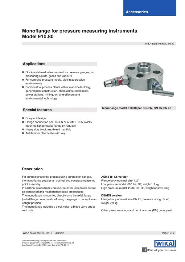
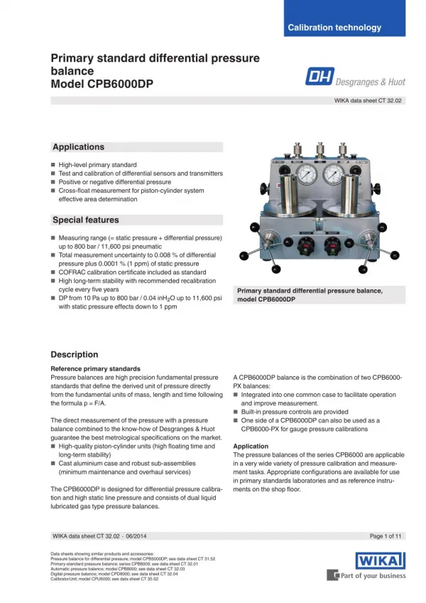
Calibration technology Primary standard differential pressure balance Model CPB6000DP WIKA data sheet CT 32.02 Applications ■ High-level primary standard ■ Test and calibration of differential sensors and transmitters ■ Positive or negative differential pressure ■ Cross-float measurement for piston-cylinder system effective area determination Special features ■ Measuring range (= static pressure + differential pressure) up to 800 bar / 11,600 psi pneumatic pressure plus 0.0001 % (1 ppm) of static pressure cycle every five years with static pressure effects down to 1 ppm ■ Total measurement uncertainty to 0.008 % of differential ■ COFRAC calibration certificate included as standard ■ High long-term stability with recommended recalibration Primary standard differential pressure balance, model CPB6000DP ■ DP from 10 Pa up to 800 bar / 0.04 inH2O up to 11,600 psi Description Reference primary standards Pressure balances are high precision fundamental pressure standards that define the derived unit of pressure directly from the fundamental units of mass, length and time following the formula p = F/A. A CPB6000DP balance is the combination of two CPB6000- PX balances: and improve measurement. CPB6000-PX for gauge pressure calibrations ■ Integrated into one common case to facilitate operation ■ Built-in pressure controls are provided ■ One side of a CPB6000DP can also be used as a The direct measurement of the pressure with a pressure balance combined to the know-how of Desgranges & Huot guarantee the best metrological specifications on the market. long-term stability) (minimum maintenance and overhaul services) ■ High-quality piston-cylinder units (high floating time and Application The pressure balances of the series CPB6000 are applicable in a very wide variety of pressure calibration and measure- ment tasks. Appropriate configurations are available for use in primary standards laboratories and as reference instru- ments on the shop floor. ■ Cast aluminium case and robust sub-assemblies The CPB6000DP is designed for differential pressure calibra- tion and high static line pressure and consists of dual liquid lubricated gas type pressure balances. WIKA data sheet CT 32.02 ∙ 06/2014 Page 1 of 11 Data sheets showing similar products and accessories: Pressure balance for differential pressure; model CPB5000DP; see data sheet CT 31.52 Primary-standard pressure balance; series CPB6000; see data sheet CT 32.01 Automatic pressure balance; model CPB8000; see data sheet CT 32.03 Digital pressure balance; model CPD8000; see data sheet CT 32.04 CalibratorUnit; model CPU6000; see data sheet CT 35.02
Operating principle The CPB6000DP consists of two piston-cylinder units. One piston-cylinder unit measures the static pressure in the system and the other one measures the differential pressure. For measuring the differential pressure, a piston-cylinder system with a minor manufacturing tolerance and a high repeatability is required in order to achieve a low measurement uncertainty. ■ Contingent error on the equilibrium between the comparison and measuring piston. This term is a function of the static pressure. piston-cylinder system. ■ Uncertainty on the effective area and masses on the Lubrication reservoir The test procedure is as follows: First the same static pressure is generated at both piston-cylinder systems. Next, as many fine increment masses are applied on the piston-cylinder system measuring the static pressure until both pistons are in their middle floating position. Following this, both piston-cylinder systems are isolated from each other, and the masses generating the differential pressure are applied on the second piston. Both systems are now maintained in their floating positions with the help of the volume slide. This procedure compensates for any diaphragm movement of the test item generated by the pressure. Piston Oil Gas pressure The exceptional intrinsic characteristics of the piston cylinders make it possible to provide and maintain a static pressure with high precision. The stability of the static pressure is much better than the measurement uncertainty of each of the two cross-sectional areas of the pistons. Oil lubricated piston cylinder principle Stability of the differential pressure Today’s sophisticated differential pressure transmitters and transducers offer resolutions makes it possible to observe the stability with which a floating piston controls a pressure. The “noise” in the two pressures defined by the two pistons of a CPB6000DP pressure balance may appear large relative to the differential pressure even though it is extremely small relative to the static pressure. Easy operation The pressure setting is done from external pressure supply via a metering valve. For fine adjustment, a very precisely- controllable spindle pump is fitted, with a precision spindle running within it. As soon as the measuring system reaches equilibrium, there is a balance of forces between the pressure and the mass load applied. The excellent quality of the system ensures that this pressure remains stable over several minutes, so that the pressure value for comparative measurements can be read without any problems, or also so that more complex adjustments can be carried out on the test item. Indeed, controlling a differential pressure of 8 mbar ... 100 bar / 0.116 ... 1,450 psi with a stability of 8 Pa means controlling two independent pressures (nominally 100 bar / 1,450 psi on the low side and 100.01 bar / 1,451.45 psi on the high side) within 1 part per million. Generally, when the pistons of a CPB6000DP pressure balance are rotating freely the noise on the differential pressure will be less than the static pressure effect’s contribution to the uncertainty statement. Measurement uncertainty As with all Desgranges & Huot pressure balances, this is defined as the difference between the measured pressure and the true value, and includes all possible sources of uncertainty. This “noise”, however, will be cyclical and consistent in nature at roughly the same frequency as the rate of rotation of the pistons except when the piston drive mechanism gives the piston an impulse. If the cyclical noise from free piston rotation is averaged and the spikes from the piston drives discarded, a precision well inside the uncertainty statements can be obtained. When calibrating high-resolution test items with rapid response times, users that follow these recommendations report that the achievable precision is three to four times greater than the uncertainty claimed. The uncertainty with which the differential pressure may be defined depends upon three separate terms: cylinder system that has been determined in Desgranges & Huot laboratories. ■ Function of piston-cylinder-system: sensitivity piston- Page 2 of 11 WIKA data sheet CT 32.02 ∙ 06/2014
The piston-cylinder system assembly Piston-cylinder systems inter-changeability Numerous inter-changeable piston-cylinder systems are available for each type of CPB6000 making possible multiple ranges with a single instrument. In all cases, changing the piston-cylinder systems requires no major disassembly. The only tool used is a special tool supplied with the standard. The maximum time required to change a piston-cylinder system is less than 1 minute. Protecting the piston In order to avoid risk of interference with the piston’s vertical mobility, the masses must be loaded directly onto the piston. Piston-cylinder system assembly Changing the piston-cylinder system This is accomplished by loading the masses onto a mass loading bell that rests directly on a plate into which the piston is fitted. When the piston is floating the piston and the mass load are completely free and there is no possibility of unintended friction or interference with their free movement. Kn conversion factor What is the Kn factor? All piston-cylinder units and masses mountable on CPB6000 pressure balances are built around a nominal mass to pressure conversion coefficient Kn. The nominal effective area of each piston-cylinder size is such that, under standard conditions, the piston loaded with 1 kg of mass will generate a pressure equivalent to the Kn value. When the piston is at the bottom of its stroke the piston plate rests on the drive pulley and rotates with it. When the piston is at the top of its stroke, the piston plate’s movement is arrested by three travel limit pins that are set into the pulley. In either position, even if the motor is on and the piston is rotating, there is no friction point. All mass values, including the mass of the piston and of the mass loading bell are adjusted to be a whole number or fraction of the kilogram. Maximum mass can be loaded with no pressure applied or maximum pressure can be applied with no mass loaded without risk of damage to the instrument or injury to the operator. The nominal pressure defined by any model CPB6000 is calculated as Kn multiplied by the mass loaded in kg. Corrections are applied to Kn to calculate the pressure defined within the uncertainty budget of the model CPB6000 used. Lubrication mode There are two main types of measuring posts: The re-entrant measuring post accepts piston-cylinder systems with nominal diameter from 1.6 ... 11.2 mm. ■ Free deformation mode ■ Re-entrant mode The use of Kn and whole number masses in no way affects the traditional pressure equation or the factors that affect a pressure measurement made with a pressure balance. Kn is the basis of a coherent relationship between mass, effective area and pressure throughout the CPB6000 series. It is intended as a tool that reduces operator confusion and errors by simplifying the calculation of mass loads and measured pressures. WIKA data sheet CT 32.02 ∙ 06/2014 Page 3 of 11
The piston cylinder „heart of the system“ The piston-cylinder system is the heart of the pressure balances and the key to its performance. The homogeneity of tungsten carbide permits ultra-precise finishing of the piston-cylinder systems. Deviation from ideal geometry is generally less than 0.1 micron (4 micro-inches). The radial clearance between piston and cylinder can be controlled very closely and varied from about 0.2 ... 1 micron (8 ... 40 micro-inch) depending on the clearance required to achieve optimum performance. The smaller diameter pistons are also available in special tool steel with minimal effect on performance since the most active element is the cylinder, which is always in tungsten carbide. Force F Cross-sectional area A Pressure p Fig. left: Oil operated piston-cylinder system Fig. right: Gas operated liquid lubricated piston-cylin- der system The basic principle of piston-cylinder systems p = F/A Multiple sizes There are 7 different types of CPB6000 piston-cylinder sizes. This range of sizes includes the largest and the smallest diameters available in high precision pressure balances. The benefit is that it is possible to select the size from a very wide range of sizes, which is suited best for the desired pressure range and further requirements. Small diameters provide a high pressure to mass ratio which saves the user from having to manipulate excessive amounts of masses and helps to miniaturize the overall system. A: Piston B: Piston head C: Rotation pin D: Cylinder Diverse piston-cylinder systems Materials and machining In most cases, both piston and cylinder are made of tungsten carbide which is both extremely hard and wear resistant. Tungsten carbide has a Young’s modulus of about 6 x 10¹¹ N/m² and a linear thermal expansion coefficient of 4.5 x 10⁻⁶/°C. Deformation due to pressure is very low and the effect of temperature is small. Page 4 of 11 WIKA data sheet CT 32.02 ∙ 06/2014
The mass set Four different mass sets are available ranging from 1 kg to 40 kg. Masses are machined out of 304 L non-magnetic stainless steel. All individual masses are whole numbers or fractions of the kilogram and are adjusted to their nominal values within the tolerance of their accuracy class. The different accuracy classes are defined as needed to achieve certain nominal accuracies on pressure. Each mass set is delivered in sturdy and attractive cabinets that are easily transportable. The kilogram The unit of mass used is always the kilogram because the kilogram is the SI unit and the national and international standard for mass from which all other mass units are derived. The kilogram also offers the convenience of being based on the decimal system, which facilitates mass totalling and data reduction. Adjustment and interchangeability Adjusting each mass to its nominal value within the tolerance of its accuracy class allows complete mass interchangeability within one set as well as among different sets. Piston- cylinder systems are not married to specific mass sets. The masses do not need to be loaded in a prescribed sequence. Furthermore, it is not necessary to calculate the mass load in a complex way using different mass values for each mass. Whole number masses are much easier to verify and recalibrate than odd values. The advantages of adjusted masses are great and their use never significantly compromises the uncertainty ultimately achieved on pressure. Main masses of CPB6000 mass sets Main masses of CPB6000 mass sets Reference mass sets Reference mass sets made up of solid polished masses of the same shape and materials as CPB6000 masses can be supplied. These are convenient as in house standards for local verification or recalibration of CPB6000 mass sets. Mass set configuration All mass sets include a number of main masses of 2 or 5 kg as well as 1 kg and fractions of the kilogram down to 0.01 g. All pistons have a mass of 200 g and all loading bells a mass of 800 g. The minimum load then is 200 g and the piston loaded with the bell has a mass of 1 kg. A 5, 4, 2, 1 progression of mass values is used making it possible to load any value desired with a resolution of 0.01 g at any point in the range. Each mass is identified with the mass set serial number as well as with an individual number within the set. Pressure progression The configuration of the mass sets allows a binary progression. ■ First measuring point: piston ■ Second measuring point: piston + bell ■ Then any point up to full scale with a resolution of 100 mg Mass loading The 5, 2 and 1 kg masses are discs with a central hole which are loaded onto the mass carrying bell. The smaller masses are loaded onto the piston plate. The majority of the load is therefore below the centre of gravity of the piston and the entire load is well centred on the vertical axis of the piston- cylinder system. Standard composition and custom sets The composition of the standard CPB6000 mass sets does not include the piston assembly (200 g) and the bell (800 g). Individual masses can be added to a mass set at any time. If so desired, a unique custom mass set may be composed from standard masses. WIKA data sheet CT 32.02 ∙ 06/2014 Page 5 of 11
CPB6000DP variants and available pressure ranges Availables ranges The CPB6000DP’s pressure measuring ranges depend on the specific Kn coefficient of the piston-cylinder assembly. Various piston cylinder assemblies can be used with a same CPB6000DP in order to adapt the standard to several applications. Pneumatic pressure balance with oil lubrication, model CPB6000 Pressure range: up to 800 bar Mass set: up to 40 kg Static pressure (SP) Effect 2) Measure- ment uncer- tainties 1) on ∆P Mini- mum ∆P range [bar] Available pressure ranges in bar Piston- cylinder unit KN [bar] Correspondence mass [kg] / pressure [bar] Unitary weight in kg First point Complete mass set in kg 1 Maximum pressure in bar 5 100 20 30 40 Piston Unit Bell 5 4 2 1 0.5 0.2 0.1 5 bar/kg 1 150 200 10 Pa + 1 ppm of SP 40 Pa + 1 ppm of SP 80 Pa + 1 ppm of SP 0.002 % of ∆P 0.002 % of ∆P 0.002 % of ∆P 0.05 25 20 10 5 2.5 1 0.5 1 4 bar 10 bar/kg 2 10 200 300 400 0.1 50 40 20 10 5 2 1 2 8 bar 20 bar/kg 4 20 400 600 800 0.2 100 80 40 20 10 4 2 4 16 bar Static pressure (SP) Effect 2) Measure- ment uncer- tainties 1) on ∆P Mini- mum ∆P range [psi] Available pressure ranges in psi Piston- cylinder unit KN [psi] Correspondence mass [kg] / pressure [psi] Unitary weight in kg First point Complete mass set in kg 1 Maximum pressure in psi 100 2,000 3,000 4,000 20 30 40 Piston Unit Bell 5 4 2 1 0.5 0.2 0.1 100 psi/kg 20 0.002 psi + 1 ppm of SP 0.008 psi + 1 ppm of SP 0.002 % of ∆P 0.002 % of ∆P 0.002 % of ∆P 0.002 % of ∆P 0.001 500 400 200 100 50 20 10 20 4 psi 200 psi/kg 40 200 4,000 6,000 8,000 0.002 1,000 800 400 200 100 40 20 40 8 psi 250 psi/kg 50 250 5,000 7,500 10,000 0.009 psi + 0.0025 1,250 1,000 500 250 125 50 25 50 16 psi 1 ppm of SP 300 psi/kg 60 300 6,000 9,000 12,000 0.01 psi + 0.003 1,500 1,200 600 300 150 60 30 60 240 psi 1 ppm of SP 1) The total measurement uncertainty is defined as the uncertainty in measurement attributed via the reference standard uncertainty, influence of environmental conditions, resolution of the instrument, repeatability and hysteresis characteristics during the measurement with the coverage factor k = 2. The static pressure effect is typically defined as A + 1 ppm of ∆P: A being the “noise” of the piston (= pressure perturbation caused by the rotation o the piston). 1 ppm of ∆P being the sensitivity of the pressure balance (= smallest value detectable by variation of the differential pressure). 2) WIKA data sheet CT 32.02 ∙ 06/2014 Page 6 of 11
Specifications Model CPB6000DP Instrument base Pressure transmission medium Lubrication medium Any non-corrosive gas Standard: Drosera™ oil Option: Krytox™ when oxygen compatibility required Piston-cylinder system Pressure ranges 0.2 ... 800 bar / 0.013 ... 11,600 psi Material Tungsten carbide Assembly type Piston position monitoring Liquid lubricated gas type (re-entrant) Standard: Dual mechanical Option: electronic Up to 40 kg Mass set Material AISI316 austenitic, non magnetic stainless steel Drop rate approx. 15 minutes (may vary depending on piston cylinder range) Case Dimension (L x W x H) 620 x 500 x 510 mm / 24.4 x 19.4 x 20.1 inch Weight 45 kg EC conformity and certificates EC conformity Pressure equipment directive 97/23/EC (Module A) Certificate Calibration Standard: COFRAC calibration certificate Option: LNE/PTB calibration certificate All Desgranges & Huot equipments are delivered with calibration certificate issued by our Cofrac accredited laboratory. Transport dimensions for complete instrument The complete instrument, in its standard version and standard scope of delivery, consists of one package for the instrument base with the following dimensions and weights. Box with base and standard accessories Dimensions: 780 x 650 x 750 mm Weight in kg net Instrument base Model gross CPB6000-DP 85 106 WIKA data sheet CT 32.02 ∙ 06/2014 Page 7 of 11
Pneumatic circuit 1 2 3 4 5 6 7 Gas inlet quick connecting head Inlet valve Exhaust valve HP isolation valve LP isolation valve Pressure manifold/sump Variable volume 8 9 10 Filter 11 Measuring piston-cylinder unit (static P + DP) 12 Comparison piston-cylinder unit (static P) 13 HP pressure connection 14 LP pressure connection Visible level lubricant reservoir Pressure gauge Page 8 of 11 WIKA data sheet CT 32.02 ∙ 06/2014
Dimensions in mm (without masses) Front view Side view 1 1 2 2 4 3 3 5 7 6 8 Top view 9 10 11 12 (1) (2) (3) (4) (5) (6) Test item connection Oil lubrication visible reservoir Piston-cylinder system Reference level High-pressure shut-off valve Low-pressure shut-off valve (7) (8) (9) (10) Level (11) Carrying handle (12) Variable volume Star handle Levelling feet Sump drain cock WIKA data sheet CT 32.02 ∙ 06/2014 Page 9 of 11
Further pressure balances within our calibration technology programme Primary-standard pressure balance, model CPB6000 Measuring ranges: ■ Pneumatic ■ Hydraulic Measurement uncertainty: up to 1,000 bar up to 5,000 bar down to 0.002 % of reading depending on model Primary-standard pressure balance, series CPB6000 For specifications see data sheet CT 32.01 Automatic pressure balance, model CPB8000 Measuring ranges: ■ Pneumatic ■ Hydraulic Measurement uncertainty: up to 1,000 bar up to 5,000 bar 0.005 % of measured value up to 0.003 % of measured value (optional) Automatic pressure balance, model CPB8000 For specifications see data sheet CT 32.03 Digital pressure balance, model CPD8000 Measuring ranges: ■ Pneumatic Measurement uncertainty: up to 500 bar 0.005 % of measured value up to 0.002 % of measured value (optional) Digital pressure balance, model CPD8000 For specifications see data sheet CT 32.04 Page 10 of 11 WIKA data sheet CT 32.02 ∙ 06/2014
Scope of delivery Options ■ Base ■ Piston-cylinder system with overhang (bell jar) ■ Set of masses manufactured to standard gravity (9.80665 m/s²) oxygen compatible version system ■ LNE/PTB calibration certificate ■ Large choice of pressure adapters ■ Gas booster ■ Remote piston position monitoring ■ 1 litre of Drosera oils as standard 60 ml of Krytox oil when ■ Tool and first level maintenance set ■ Operating instructions in German and English language ■ COFRAC calibration certificate ■ Storage case for the base, mass set and piston-cylinder Ordering information Model / Instrument version / Accuracy / Set of 2 piston-cylinder assemblies / Set of 2 mass sets / Terminal 5000 / Calibration for differnetial pressure balance / Additional order information © 2014 WIKA Alexander Wiegand SE & Co. KG, all rights reserved. The specifications given in this document represent the state of engineering at the time of publishing. We reserve the right to make modifications to the specifications and materials. WIKA data sheet CT 32.02 ∙ 06/2014 Page 11 of 11 06/2014 GB WIKA Alexander Wiegand SE & Co. KG Alexander-Wiegand-Straße 30 63911 Klingenberg/Germany Tel. +49 9372 132-0 Fax +49 9372 132-406 info@wika.de www.wika.de