Download
1 / 2
20 likes | 167 Views
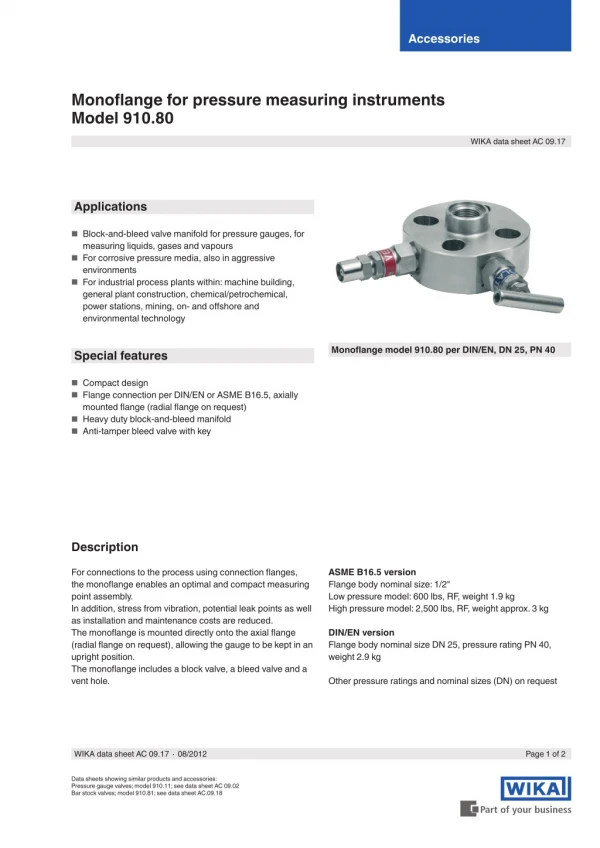
For connections to the process using connection flanges, the monoflange enables an optimal and compact measuring point assembly. In addition, stress from vibration, potential leak points as well as installation and maintenance costs are reduced. The monoflange is mounted directly onto the axial flange (radial flange on request), allowing the gauge to be kept in an upright position. The monoflange includes a block valve, a bleed valve and a vent hole.<br>For More Information visit on:- www.seeautomation.com<br>Our Mail I.D:- sales@seeautomation.com<br>Contact Us:- 91-11-22012324 , 8144883403<br>

E N D
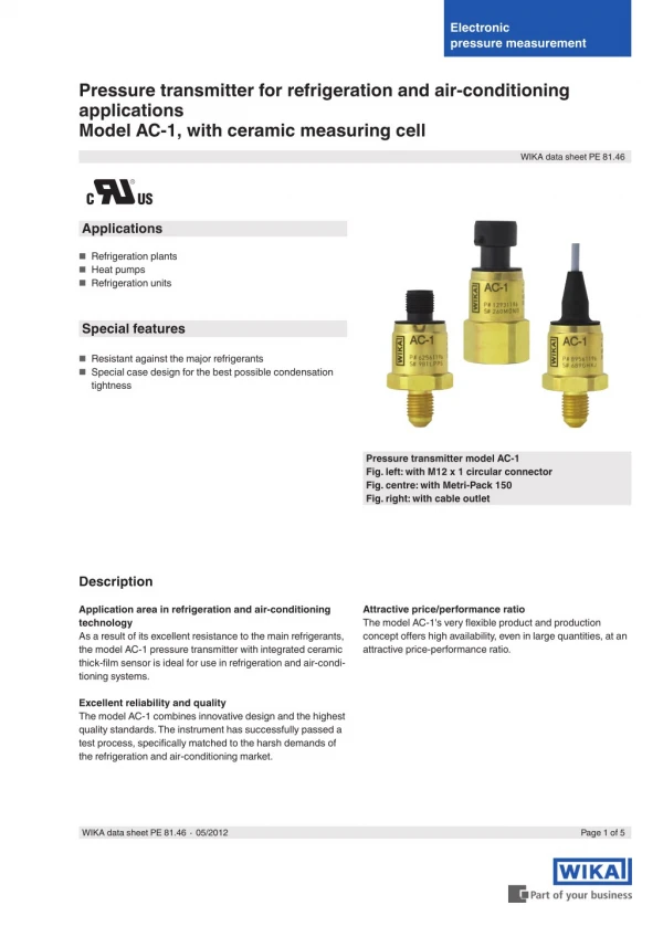
Accessories Monoflange for pressure measuring instruments Model 910.80 WIKA data sheet AC 09.17 Applications ■ Block-and-bleed valve manifold for pressure gauges, for measuring liquids, gases and vapours environments general plant construction, chemical/petrochemical, power stations, mining, on- and offshore and environmental technology ■ For corrosive pressure media, also in aggressive ■ For industrial process plants within: machine building, Monoflange model 910.80 per DIN/EN, DN 25, PN 40 Special features ■ Compact design ■ Flange connection per DIN/EN or ASME B16.5, axially mounted flange (radial flange on request) ■ Heavy duty block-and-bleed manifold ■ Anti-tamper bleed valve with key Description ASME B16.5 version Flange body nominal size: 1/2" Low pressure model: 600 lbs, RF, weight 1.9 kg High pressure model: 2,500 lbs, RF, weight approx. 3 kg For connections to the process using connection flanges, the monoflange enables an optimal and compact measuring point assembly. In addition, stress from vibration, potential leak points as well as installation and maintenance costs are reduced. The monoflange is mounted directly onto the axial flange (radial flange on request), allowing the gauge to be kept in an upright position. The monoflange includes a block valve, a bleed valve and a vent hole. DIN/EN version Flange body nominal size DN 25, pressure rating PN 40, weight 2.9 kg Other pressure ratings and nominal sizes (DN) on request WIKA data sheet AC 09.17 ∙ 08/2012 Page 1 of 2 Data sheets showing similar products and accessories: Pressure gauge valves; model 910.11; see data sheet AC 09.02 Bar stock valves; model 910.81; see data sheet AC.09.18
Standard version Dimensions in mm Position of process connection Design for axially-mounted flanges (radial on request) ASME B16.5 version Pressure gauge connection Block-and-bleed valve ■ Valves with external spindle thread ■ Rolled valve spindle with pivoted double cone ■ Anti-tamper bleed valve with key Smooth-finished sealing face Bleed valve Pressure gauge connection Thread ½ NPT female Block valve 11267276N.01 Vent connection Thread ¼ NPT female Venting Material specification Body, bonnet and spindle: Stainless steel Pivoted double cone: Gland packing: Stainless steel PTFE All dimensions per ASME B16.5 Low pressure model, 600 lbs High pressure model, 2,500 lbs Order No.: 11267276 Order No.: 11267284 Options DIN/EN version Pressure gauge connection ■ Design for vertically-mounted flanges ■ 3.1 material test certificate per EN 10204 ■ Other materials Sealing face per DIN 2526 Bleed valve Block valve 11267292N.01 Venting Order No.: 11267292 Ordering information To order the described product the given order number is sufficient. Other options require additional specification. © 2007 WIKA Alexander Wiegand SE & Co. KG, all rights reserved. The specifications given in this document represent the state of engineering at the time of publishing. We reserve the right to make modifications to the specifications and materials. Page 2 of 2 WIKA data sheet AC 09.17 ∙ 08/2012 08/2012 GB WIKA Alexander Wiegand SE & Co. KG Alexander-Wiegand-Straße 30 63911 Klingenberg/Germany Tel. (+49) 9372/132-0 Fax (+49) 9372/132-406 E-mail info@wika.de www.wika.de