Download
1 / 12

E N D
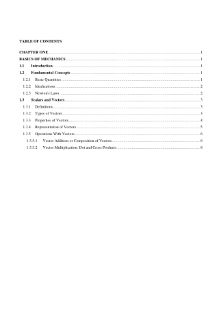
TABLE OF CONTENTS CHAPTER ONE ................................................................................................................................................... 1 BASICS OF MECHANICS .................................................................................................................................. 1 1.1 Introduction............................................................................................................................................... 1 1.2 Fundamental Concepts ............................................................................................................................. 1 1.2.1 Basic Quantities ...................................................................................................................................... 1 1.2.2 Idealizations ............................................................................................................................................ 2 1.2.3 Newton's Laws ........................................................................................................................................ 2 1.3 Scalars and Vectors ................................................................................................................................... 3 1.3.1 Definitions .............................................................................................................................................. 3 1.3.2 Types of Vectors ..................................................................................................................................... 3 1.3.3 Properties of Vectors ............................................................................................................................... 4 1.3.4 Representation of Vectors ........................................................................................................................ 5 1.3.5 Operations With Vectors ......................................................................................................................... 6 1.3.5.1 Vector Addition or Composition of Vectors ..................................................................................... 6 1.3.5.2 Vector Multiplication: Dot and Cross Products ................................................................................ 8
HU, IoT, Department of civil Engineering Engineering Mechanics - I CHAPTER ONE BASICS OF MECHANICS 1.1Introduction Mechanics is a branch of the physical sciences that is concerned with the state of rest or motion of bodies that are subjected to the action of force. In general, this subject can be subdivided into three branches: rigid-body mechanics, deformable-body mechanics, and fluid mechanics. In this course we will study rigid-body mechanics since it is a basic requirement for the study of the mechanics of deformable bodies and the mechanics of fluids. Rigid-body mechanics is divided into two areas: statics and dynamics. Statics deals with the equilibrium of bodies, that is, those that are either at rest or move with a constant velocity; whereas dynamicsis concerned with the accelerated motion of bodies. We can consider statics as a special case of dynamics, in which the acceleration is zero. 1.2Fundamental Concepts Before we begin our study of engineering mechanics, it is important to understand the meaning of certain fundamenta1 concepts and principles. 1.2.1Basic Quantities The following four quantities are used throughout mechanics. a)Length: Length is used to locate the position of a point in space and thereby describe the size of a physical system. Once a standard unit of length is defined, one can then use it to define distances and geometric properties of a body as multiples of this unit. b)Time: Time is conceived as a succession of events. Although the principle of statics is time independent, this quantity plays an important role in the study of dynamics. c)Mass: Mass is a measure of a quantity of matter that is used to compare the action of one body with that of another. This property manifests itself as a gravitational attraction between two bodies and provides a measure of the resistance of matter to a change in velocity. d)Force: In general force is a Push or Pull, which creates motion or tends to create motion, destroy or tends to destroys motion. In engineering mechanics force is the action of one body on another. A force tends to move a body in the direction of its action, a force is characterized by its point of application, magnitude, and direction, i.e. a force is a vector quantity. 1 Lecture Note
HU, IoT, Department of civil Engineering Engineering Mechanics - I 1.2.2Idealizations Models or idealizations are used in mechanics in order to simplify application of the theory. Here we will consider three important idealizations. a)Particle:A particle may be defined as a body (object) has mass but no size (neglected), such body cannot exists theoretically, but when dealing with problems involving distance considerably larger when compared to the size of the body. In the mathematical sense, a particle is a body whose dimensions are considered to be near zero so that it analyze as a mass concentrated at a point. A body may tread as a particle when its dimensions are irrelevant to describe its position or the action of forces applied to it. For example the size of earth is insignificant compared to the size of its orbits and therefore the earth can be modeled as a particle when studying its orbital motion. When a body is idealized as a particle, the principles of mechanics reduce to rather simplified form since the geometry of the body will not be involved in the analysis of the problem. b)Rigid Body:A rigid body may be defined a body in which the relative positions of any two particles do not change under the action of forces means the distance between two points/particles remain same before and after applying external forces. As a result the material properties of anybody that is assumed to be rigid will not have to be considered while analyzing the forces acting on the body. In most cases the actual deformations occurring in the structures, machines, mechanisms etc are relatively small and therefore the rigid body assumption is suitable for analysis c)Concentrated Force: A Concentrated Force represents the effect of a loading which is assumed to act at a point on a body. We can represent a load by a concentrated force, provided the area over which the load is applied is very small compared to the overall size of the body. An example would be the contact force between a wheel and the ground. 1.2.3Newton's Laws The three laws of Newton are of importance while studying mechanics. Sir Isaac Newton was the first to state correctly the basic laws governing the motion of a particle and to demonstrate their validity. Slightly reworded with modern terminology, these laws are: ?Law I A particle remains at rest or continues to move with uniform velocity (in a straight line with a constant speed) if there is no unbalanced force acting on it. ?Law II The acceleration of a particle is proportional to the vector sum of forces acting on it, and is in the direction of this vector sum. 2 Lecture Note
HU, IoT, Department of civil Engineering Engineering Mechanics - I ?Law III The forces of action and reaction between interacting bodies are equal in magnitude, opposite in direction, and collinear (they lie on the same line). The first and third laws have of great importance for Statics whereas the second one is basic for dynamics of Mechanics. Another important law for mechanics is the Law of gravitation by Newton, as it usual to compute the weight of bodies. Accordingly: ? = ????? ?? Thus the weight of a mass ‘m’ ? = ?? 1.3Scalars and Vectors 1.3.1Definitions Aftergenerally understanding quantities as Fundamental or Derived, we shall also treat them as either Scalars or Vectors. I)Scalar Quantities: - are physical quantities that can be completely described (measured) by their magnitude alone. These quantities do not need a direction to point out their application (Just a value to quantify their measurability). They only need the magnitude and the unit of measurement to fully describe them. Examples of scalar quantities areTime[s], Mass [Kg], Area [m2], Volume [m3], Density [Kg/m3], Distance [m], etc. II)Vector Quantities: - Like Scalar quantities, Vector quantities need a magnitude. But in addition, they have a direction, and sometimes point of application for their complete description. Vectors are represented by short arrows on top of the letters designating them. Examples of vector quantities are Force [N, Kg.m/s2], Velocity [m/s], Acceleration [m/s2], Momentum [N.s, kg.m/s], etc. 1.3.2 Types of Vectors Vectors representing physical quantities can be classified as free, sliding, or fixed. ?A free vectoris one whose action is not confined to or associated with a unique line in space. For example, if a body moves without rotation, then the movement or displacement of any point in the body may be taken as a vector. This vector describes equally well the direction and magnitude of the displacement of every point in the body. Thus, we may represent the 3 Lecture Note
HU, IoT, Department of civil Engineering Engineering Mechanics - I displacementof such a body by a free vector. Examples of free vector are Displacement, Velocity, Acceleration, Couples, etc. ?A sliding vectorhas a unique line of action in space but not a unique point of application. For example, when an external force acts on a rigid body, the force can be applied at any point along its line of action without changing its effect on the body as a whole, and thus it is a sliding vector. (i.e. force can be applied anywhere along its line of action on a rigid body without altering its external effect on the body. This principle is known as Principle of Transmissibility) ?A fixed vectoris one for which a unique point of application is specified. The action of a force on a deformable or non-rigid body must be specified by a fixed vector at the point of application of the force. In this instance the forces and deformations within the body depend on the point of application of the force, as well as on its magnitude and line of action 1.3.3Properties of Vectors i)Equality of vectors: Two free vectors are said to be equal if and only if they have the same magnitude and direction. B C A ii)The Negative of a vector: is a vector which has equal magnitude to a given vector but opposite in direction. A -A iii)Null vector: is a vector of zero magnitude. A null vector has an arbitrary direction. iv)Unit vector: is any vector whose magnitude is unity. A unit vector along the direction of a certain vector, say vector A (denoted by uA) can then be found by dividing vector A by its magnitude. ??=? ? Generally, any two or more vectors can be aligned in different manner. But they may be: * Collinear:- Having the same line of action. * Coplanar:- Lying in the same plane. * Concurrent:- Passing through a common point. 4 Lecture Note
HU, IoT, Department of civil Engineering Engineering Mechanics - I 1.3.4Representation of Vectors A) Graphical representation A vector quantity V is represented by a line segment, Fig. 1/1, having the direction of the vector (i.e. measured by an angle θ θ from some known reference direction) and having an arrowhead to indicate the sense. The length of the directed line segment represents to some convenient scale the magnitude /V/ of Figure 1/1 the vector and is printed with lightface italic type V. In scalar equations, and frequently on diagrams where only the magnitude of a vector is labeled, the symbol will appear in lightface italic type. Boldface type is used for vector quantities whenever the directional aspect of the vector is a part of its mathematical representation. When writing vector equations, always be certain to preserve the mathematical distinction between vectors and scalars. In handwritten work, use a distinguishing mark for each vector quantity, such as an arrow over the symbol, ???, to take the place of boldface type in print. B) Algebraic (Arithmetic) Representation Algebraically a vector is represented by the components of the vector along the three dimensions. In this way both the magnitude and direction of the vector are conveniently contained in one mathematical expression. In many problems, particularly three-dimensional ones, it is convenient to express the rectangular components of V, Fig. 1/2, in terms of unit vectors i, j, and k, which are vectors in the x-, y-, and z-directions, respectively, with unit magnitudes. Because the vector V is the vector sum of the components in the x-, y-, and z-directions, we can express V as follows: Figure 1/2 ? = ??? ? ??? ? ??? We now make use of the direction cosinesl, m, and n of V, which are defined by ? = ????? ? = ????? ? = ????? Thus, we may write the magnitudes of the components of V as ??= ?? ??= ?? ??= ?? where, from the Pythagorean theorem, ?? ?? ?? ?? ? ??= ?? 5 Lecture Note
HU, IoT, Department of civil Engineering Engineering Mechanics - I Note that this relation implies that ??? ??? ??= 1. 1.3.5Operations with Vectors Scalar quantities are operated in the same way as numbers are operated. But vectors are not and have the different rules. Decomposition is the process of getting the components of a given vector along some other different axis. Practically decomposition is the reverse of composition. Any two or more vectors whose sum equals a certain vector Vare said to be the components of that vector. Thus, the vectors V1and V2in Fig. 1/3a are the components of V in the directions 1 and 2, respectively. It is usually most convenient to deal with vector components which are mutually perpendicular; these are called rectangular components. Figure 1/3 The vectors Vxand Vyin Fig. 1/3b are the x- and y-components, respectively, of V. Likewise, in Fig. 1/4c, Vx'and Vy'are the x'- and y'- components of V. When expressed in rectangular components, the direction of the vector with respect to, say, the x-axis is clearly specified by the angle θ,where ? = tan#??? ?? 1.3.5.1 Vector Addition or Composition of Vectors Composition of vectors is the process of adding two or more vectors to get a single vector, a Resultant, which has the same external effect as the combined effect of individual vectors on the rigid body they act. There are different techniques of adding vectors. 6 Lecture Note
HU, IoT, Department of civil Engineering Engineering Mechanics - I A) Graphical Method Vectors must obey the parallelogram law of combination. This lawstates that two vectors V1and V2, treated as free vectors, Fig. 1/4a, may be replaced by their equivalent vector V, which is the diagonal of the parallelogram formed by V1and V2 as its two sides, as shown in Fig.1/4b. This combination is called the vector sum, and is represented by the vector equation ? = ?$? ?% where the plus sign, when used with the vector quantities (in boldface type), means vector and not scalar addition. The scalar sum of the magnitudes of the two vectors is written in the usual way as V1 '* + V2. The geometry of the parallelogram shows that V ≠ V1+ V2. Once the parallelogram is drawn to scale, the magnitude of the resultant can be found by measuring the diagonal and converting it to magnitude by the appropriate scale. The direction of the resultant with respect to one of the vectors can be found by measuring the angle the diagonal makes with that vector. Figure 1/4 The two vectors V1and V2, again treated as free vectors, may also be added head-to-tail by the triangle law, as shown in Fig. 1/4c, to obtain the identical vector sum V. We see from the diagram that the order of addition of the vectors does not affect their sum, so that V1+ V2= V2 + V1 The difference V1- V2 between the two vectors is easily obtained by adding - V2 to V1 as shown in Fig. 1/5, where either the triangle or parallelogram procedure may be used. The difference V' between the two vectors is expressed by the vector equation ?&= ?$' ?% Figure 1/5 where the minus sign denotes vector subtraction. 7 Lecture Note
HU, IoT, Department of civil Engineering Engineering Mechanics - I Thus the Triangle rule can be extended to more than two vectors as, “If a system of vectors are joined head to tail, their resultant will be the vector that completes the polygon so formed, and it starts from the tail of the first vector and ends at the head of the last vector.” B) Analytic Method (Trigonometric Rules) The analytic methods are the direct applications of the above postulates and theorems in which the resultant is found mathematically instead of measuring it from the drawings as in the graphical method. The resultant of two vectors can be found analytically from the parallelogram rule by applying the cosine and the sine rules. Consider the parallelogram shown in Fig. 1/6. And let θ θ be the angle between the two vectors V1and V2. Consider triangle ABC and from cosines law, ?? ?? ?' 2????cos? ??= ?? Figure 1/6 ?? ?? ?' 2????cos? ? = ,?? Where, V is the resultant of the two vectors V1and V2 Similarly, the inclination,β β, of the resultant vector from V1 can be found by using sine law sin. ?? ? C) Component Method of Vector Addition ?sin? ⟹ . ? sin#?0?? ?sin?1 This is the most efficient method of vector addition, especially when the number of vectors to be added is large. In this method first the components of each vector along a convenient axis will be calculated. The sum of the components of each vector along each axis will be equal to the components of their resultant along the respective axes. Once the components of the resultant are found, the resultant can be found by parallelogram rule as discussed above. 1.3.5.2 Vector Multiplication: Dot and Cross Products I)Multiplication of Vectors by Scalars Let n be a non-zero scalar and A be a vector, then multiplying A by n gives as a vector whose magnitude is nA and whose direction is in the direction of A if n is positive or is in opposite direction to A if n is negative. 8 Lecture Note
HU, IoT, Department of civil Engineering Engineering Mechanics - I Multiplication of vectors by scalars obeys the following rules: i)Scalars are distributive over vectors ?2? + 34 ? ?? + ?3 ii)Vectors are distributive over scalars 2? + ?4? ? ?? + ?? iii)Multiplication of vectors by scalars is associative 2??4? ? ?2??4 ? ?2??4 II)Multiplication of Vector by a Vector In mechanics there are a few physical quantities that can be represented by a product of vectors. For example: Work, Moment, etc. There are two types of products of vector multiplication a)Dot Product: Scalar Product The scalar product of two vectors A and B which are θ degrees inclined from each other denoted by A.B (A dot B) will result in a scalar of magnitude ?.3 ? ?6cos? If the two vectors are represented analytically as, ? = 7?? + 7?? + 7?? 7?8 3 = 9?? + 9?? + 9??, then ?.3 = 7?9?+ 7?9?+ 7?9? b)Cross Product: Vector Product The vector product of two vectors A and B that are θ degrees apart denoted by A x B (A cross B) is a vector of magnitude ABsinθ and direction perpendicular to the plane formed by the vectors A and B. The sense of the resulting vector can be determined by the right-hand rule. ? × 3 = ?6sin?, >??@??8A?B?7? C? Cℎ? @?7?? E????8 9F G??C??? ? 7?8 3 If the two vectors are represented analytically as, ? = 7?? + 7?? + 7?? 7?8 3 = 9?? + 9?? + 9??, then the cross product A x B will be the determinant of the three by three matrix as, i j k ? × 3 = H7?9?− 7?9?I? − 27?9?− 7?9?4? + H7?9?− 7?9?I? ax ay az bz by bx But, vector product is not commutative; in fact, ? × 3 = −3 × ? 9 Lecture Note
HU, IoT, Department of civil Engineering Engineering Mechanics - I Example 1.1 For the vectors V1and V2 shown in the Figure E1.1, (a) determine the magnitude S of their vector sum S = V1+ V2 (b) determine the angle α between S and the positive x-axis (c) write S as a vector in terms of the unit vectors i and j and then write a unit vector nS along the vector sum S (d) determine the vector difference D = V1- V2 Solution: (a)We construct to scale the parallelogram shown in Fig. E1.1(a) for adding V1and V2. Using the law of cosines, we have ?+ ?? ?' 2????cos? J ?,?? ? K4?+ 3?' 2244234cos105P? 5.59 Units (b)Using the law of sines for the lower triangle, we have sin105P 5.59 sin2S + 30P4 ? 0.692 =sin2S + 30P4 4 S ? 30P= 43.76P S = 13.76P (c)With knowledge of both S and α, we can write the vector S as V = J?? ? J?? = JcosS ? ? JsinS? ? 5.59cos13.76P? ? 5.59sin13.76P? = 5.43? ? 1.33? Units Then WV?V J?5.4.3? ? 1.33? 5.59 = 0.971? + 0.238? Units (d)The vector difference D is Figure E1.1 Y ? ?$' ?%? H???? + ????I ' H???? ' ????I ? 24cos45P? + 4sin45P?4 ' 23cos30P? ' 3sin30P?4 ? 0.230? ? 4.330? Units The vector D is shown in Fig. E1.1(b) as D = V1 + (- V2). 10 Lecture Note
HU, IoT, Department of civil Engineering Engineering Mechanics - I Example 1.2 The screw eye in Figure E1.2 (a) is subjected to two forces, F1and F2. Determine the magnitude and direction of the resultant force. Solution: Parallelogram Law: The parallelogram is formed by drawing a line from the head of F1 that is parallel to F2, and another line from the head of F2 that is parallel to F1. The resultant force FRextends to where these lines intersect at point A. Fig.E1.2 (b). The two unknowns are the magnitude of FR and the angle θ. Trigonometry Rules:From the parallelogram, the vector triangle is constructed, Fig.E1.2(c). Using the law of cosines, we have ?+ ?? ?' 2????cos? ?Z?,?? ? K100?+ 150?' 22100421504cos115P? 212.6 N Using the law of sines to determine angle θ 150 N?sin115P sin? 212.6 N 150 N 212.6 N2sin115P4 ? ? 39.8P sin? ? Thus, the direction Φ of FR, measured from the horizontal, is ∅ = ? ? 15.0P= 39.8P? 15.0P= 54.8P Figure E1.2 11 Lecture Note