Download
1 / 18
240 likes | 306 Views
Electron Beam Melting is an Additive manufacturing technique similar to Selective Laser Melting with unique capabilities

E N D
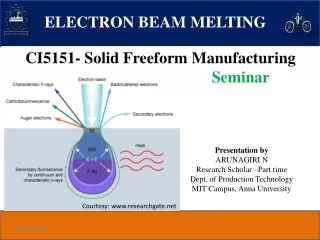
ELECTRON BEAM MELTING CI5151- Solid Freeform Manufacturing Seminar Presentation byARUNAGIRI N Research Scholar –Part time Dept. of Production Technology MIT Campus, Anna University Courtesy: www.researchgate.net
Outline Introduction Principles Processes Materials Advantages Limitations Application Reference INSIDE ELECTRON BEAM MELTING , GE Additive, EBM, White paper. 2
Introduction The Electron Beam Melting (EBM) process is similar to Selective Laser Sintering(SLS) , instead of laser beam a focused electron beam scans across a thin layer of powder. When the high-speed electrons strike the metal powder, the kinetic energy is converted into thermal energy. when the temperature is raised above the melting point of powder, the electron beam rapidly liquefies the powder. 3
Introduction Courtesy: www.pcimag.com 4
Working Principle Within the electron beam gun, a tungsten filament incandesces by electric current and emit a cloud of electrons. These electrons stream through the gun at approximately half the speed of light due to potential difference between the anode and cathode. INSIDE ELECTRON BEAM MELTING , GE Additive, EBM, White paper. 5
Working Principle Two magnetic fields organize and direct the fast- moving electrons. The first acts as a magnetic lens, which focuses the beam to the correct diameter. The second magnetic field deflects the focused beam to the target point on the powder bed. INSIDE ELECTRON BEAM MELTING , GE Additive, EBM, White paper. 6
Working Principle Additive manufacturing of metallic components by selective EBM — a review , University Erlangen-Nürnberg, Published by Informa UK Limited,C. Körner, 2016 7
Process Additive manufacturing of metallic components by selective EBM — a review , University Erlangen-Nürnberg, Published by Informa UK Limited,C. Körner, 2016 8
Process The electron beam gun is stationary, and magnetic coil is used no moving mechanical parts are needed to deflect the beam. This delivers very high scanning speeds, up to 1000 m/sec and fast build rates, up to 60 cm3/hour. The process is three to five times faster than other additive technologies. Additive manufacturing of metallic components by selective EBM — a review , University Erlangen-Nürnberg, Published by Informa UK Limited,C. Körner, 2016 9
Process The EBM parts are built inside vacuum chamber to prevent a loss of energy that would be caused by the fast moving electrons colliding with air or gas molecules. The vacuum has two advantages: The process is 95% energy-efficient, which is five to ten times greater than laser technology. The vacuum supports processing of reactive metal alloys such as titanium. 10
Materials As powder particles absorb electrons they gain an increasingly negative charge. This has two potentially detrimental effects: if the repulsive force of neighbouring negatively charged particles overcomes the gravitational and frictional forces holding them in place, there will be a rapid expulsion of powder particles from the powder bed, creating a powder cloud Increasing negative charges in the powder particles will tend to repel the incoming negatively charged electrons, thus creating a more diffuse beam. As a result, the conductivity of the powder bed in EBM must be high enough that powder particles do not become highly negatively charged. 11
Materials & Application Insert with complex cooling geometries Power plants Aero engines Tool steel Injection mould inserts Artificial joints Dental prosthesis Parts of turbo chargers Cutting tools Aerospace fuel nozzles Heat exchangers Currently, there is just one manufacturer which commercially offers installations for selective electron beam melting (Arcam AB, Sweden). Therefore, the commercial availability of materials which can be processed with SEBM is still extremely restricted at present C. Körner (2016) 12
Advantages Electrons as energy carriers - provides deep penetration and low reflection in the powder. It also allows for the electromagnetic beam control to function extremely fast. Hot process - provides low internal stress which enables production of crack prone materials, bulky parts or thin, free-floating beams to be produced. Vacuum process - enables extreme cleanliness and energy efficiency. Parts produced free floating in sintered powder – allows tight stacking of parts for high productivity and the possibility to build with no or limited support. Reusable powder. Courtesy: www.researchgate.net 13
CASE STUDY: Nickel Super alloy based turbine blades CONVENTIONAL TECHNIQUE: The production of nickel-base super alloysblades is traditionally manufactured by following process Directional Solidified (DS) and Single Crystal (SX) casting technologies. Solution heat treatment. LIMITATION IN CONVENTIONAL TECHNIQUE: Difficulty to achieve Homogeneous microstructure To cast complex geometries with cooling features 14
Need for additive manufacturing technique In conventional manufacturing techniques, the buy-to-fly ratio is about 20:1. For example, if one ton (1000 kg) of material is used in production, only 50 kg ends up in the final part. 3:1 in case of Additive manufacturing. Complex cooling systems (CS) can help improve blade heat management and improve engine Turbine Entry Temperature. Crack prone materials can be manufactured by controlled solidification. Cellular structure can be used to reduce weight without compromising mechanical properties 15
Various additive manufactured turbine blades. (a) Blade with the cooling passage at the edge, (b) blade with the cooling passage at both edge and middle part, (c) high-pressure turbine (HPT)blade,and(d)complexefficientcoolingblade
Key Points Applying specific melting strategies, the grain structure can be either columnar or equiaxed. Thus, switching from an isotropic material to a strongly anisotropic material by changing the processing parameters is possible and can be used for local optimisation of materials properties within components. Various cellular structures part with auxetic strain behaviour(negative transverse contraction) Additive manufacturing of metallic components by selective EBM — a review , University Erlangen-Nürnberg, Published by Informa UK Limited,C. Körner, 2016 17
Reference INSIDE ELECTRON BEAM MELTING , GE Additive, EBM, White paper. Additive manufacturing of metallic components by selective electron beam melting — a review , University Erlangen-Nürnberg, Published by Informa UK Limited, trading as Taylor & Francis Group, C. Körner, 2016. A Review on the Processing of Aero-Turbine Blade Using 30 Print Techniques, AyushSinha et al., Journal of Manufacturing andMaterials Processing, Accepted : 17 January 2022 . NPTEL, Turbo Machinery Engineering, Prof. BhaskarRoy, Prof. A M Pradeep, Department of Aerospace, IITBombay. Additive Manufacturing Technologies 3D Printing, Rapid Prototyping, and Direct Digital Manufacturing by Ian Gibson, David Rosen, Brent Stucker ,2015. 18