Download
1 / 19
190 likes | 219 Views
Explore the cutting-edge electron beam measurements conducted at SPARC, utilizing different types of screens like Yag:Ce single crystal for high resolution, and details on detectors, screens, RF Deflector, and LINAC beam control. Discover the latest techniques and tools used for precise measurements.

E N D
Electron Beam measurements @ SPARC Daniele Filippetto On behalf of SPARC team
SPARC LAYOUT PC Laser
e- beam detectors: • 3 different types of screens: • Optical Transition Radiation • Best resolution, no saturation, • Low Photon Yield in the visible region, need precise alignement • Single Crystal Ce:Yag • Good resolution, high photon yield centered on 500nm • Saturation, multiple scattering can limit the resolution (thickness) • Crom-ox powder • High saturation level, only visible light emitted • Poor resolution (depending on the grain size), 8-12 bit Firewire/ethernet digital camera used as detectors; Commercial Macro obj. used to image the screen on the CCD
beam imaging: Screens • Electron multiple scattering inside the screen; • Bremsstrahlung radiation creation, that generates x-rays causing scintillation • The lens diffraction; • The pixel size divide by the optical system magnification. We need to choose the screen thickness to assure the best resolution, but also the bigger signal possible (bulk effect) Yag:Ce single crystal has best resolution (that is dominated by the optical system).Linearity assured on the SPARC density range, saturation excluded. A saturation limit approx. 0.01 pC/um^2 for YAG:CE crystal has been found, while the maximum for the SPARC case is about 0.18 fC/um^2. Chosen screens: Yag:Ce single crystal with aluminum coating to assure Conduction ( the material itself is an insulator). The system resolution is a combination of all these causes:
e- beam Detectors: Resolution 100um Non intercepting; BPMs sensitivity; beam position dependency error <10-4 3E6 particles resolution (about 500fC) Non intercepting; Both low and high energy; ICT High sensitivity; beam dump; Used just for low energy; Faraday cup
RF Deflector: 5 cells standing wave, TM110 mode, 2.856 GHz Input power = 1MW Shunt Imp.=2.5 MΩ SPARC case: σz_res = 65fs = 20um (hyp σy_defl100um)
Gun diagnostics: Feedback on the RF phase and amplitude; ICT and Faraday cup; (Phase scan) Yag screen (beam centering, solenoid scan, th. emittance). 2 orthogonal slit systems (emittance) 2 bpm to control the positon of the beam injected in the LINAC; 2 screens Faraday cup Slit mask ICT BPMs
LINAC: • Orbit control and correction: • BPMs each setion entrance; • H/V Corrector magnets each section entrance/exit; • Envelope control for emittance minimization: • “Cromox” at each section exit, to image the beam. Rough • estimate of RF kick, beam envelope all along the LINAC. • Solenoids to compensate for the emittance growth (usefull expecially • in the velocity bunching setup).
TL: time ~100KeV (0.013% RMS) time ~7ps ~750KeV (0.1% RMS) energy 3 points for beam imaging (2 different screens,OTR and Ce:Yag crystal) Quadruoles for beam matching in the undulator used to measured the projected emittance Dispersive section (dipole) used to measure energy and energy spread (14 degrees,1.07 m trj. radius) RF deflector: slice emittance, slice energy spread, longitudinal Trace Space.
Cavity BPM Dipole modes are used for position detection, since their amplitude depends linearly on the beam position and is zero for a centered beam. The signals excited in the cavity are coupled into an external circuit, and the amplitude of this particular mode can be separated in the frequency domain. In principle, no additional subtraction is needed, the information about the position is given directly. High resolution because of the large signal per micron displacement. N =√Z0kTkΔf k is the Boltzmann’s constant, Tk the temperature in Kelvin Δf = f110/Qext Resolution down to nm
EO crystal Wollaston Prism s+ l/4 pol. Balanced Detector fs laser b s- e-beam Electro-Optical Technique: Γis the phase shift between the two polarization α is the angle between Ethz and the crystal axis Ea is the Thz field coming with the e-beam ZnTe or GaP Crystals are used (110 cut).
EOS Single shot schemes • SPECTRAL DECODING • Simplest implementation • Limited resolution>600fs. • TEMPORAL DECODING • Highest resolution demonstrated ~ 50 fs • Needs complex amplified laser • and laser transport • SPATIAL ENCODING • Resolution expected to be same as TD • Low power laser sufficient: e.g. femtosecond fiber lasers
EO scheme @ SPARC: Fiber receiver box (413x178x90) example of raw data for single shot measurement of short bunch @ FLASH (temporal decoding) SPARC-FERMI collaboration Pol l/2 Seed laser EO chamber concept by D.Fritz LCLS Diode- COMPRESSOR AUTO CORR Menlo Laser TC-780 75 nsec gated ICCD ICCD Cube beamsplit Delay line BBO l/4 l/2 Stretcher O2E conv.box (300x80x100) E-beam lens lens EO Longitudinal electron bunch shape Laser-electron beam jitter, with fs resolution (can be used to measure the FLAME-SPARC jitter) etalon Optical Enclosure box mot mirror, CCD Fiber link Periscope FAST DIODE Cylindircal lens Thanks to M.Veronese Mirror mirror 14
Absolute bunch length measurements by incoherent radiation fluctuation analysis A new method for bunch length measurement Photon radiation by charged particles is a stochastic process. (synchrotron radiation, transition radiation, Cherenkov radiation, …) By fixing a bandwidth sw , we define amodewith coherence length: The photons radiated by the electrons within a single mode adds coherently.
Fluctuations as function of number of modes M ~ 10 In a bunch of length σt and zero transverse size, there are M=σt /σtc independent modes radiating simultaneously. In this situation, the fluctuation of the energy radiated per pulse becomes (M combined Poisson processes): Possibility of absolute bunch length measurements !
A step more toward shorter bunches measurements In order to minimize the experimental error is good to have no more than ~ 100 modes Shorter bunches relax the requirements on the bandwidth… And because No intrinsic limit in measuring shorter and shorter bunches!
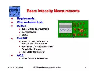
20 mV/div Measured amplitude 2 ns/div Measurement range First results: • ALS - BL 7.2 - Sept. 22, 2006 • Filter: 632.8 nm, 1 nm FWHM • APD: Perkin Elmer C30902S, Vbias = -238 V (G~100) • AMP. Ortec VT 120 G ~ 200 1.9 GeV - ICS ~ 3.7 mA Nat. bunch length = 20.3 ps
Conclusions: • the actual Photo-injector diagnostic has been tested and optimized. • All the parameters needed for the present machine goal can be measured with good accuracy. • The accuracy decreases going toward shorter and bunches and lower currents; Going toward: More sensitive, precise and accurate tools; Non interceptive systems; Using noise may help.