Download
1 / 5
50 likes | 58 Views
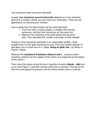
Low resistance earth and earth electrode<br><br>A good, low resistance ground electrode depends on a low resistivity ground at a location where you can insert your electrodes. There are two approaches to choosing your location:<br><br><br>How to determine the best location for the earth electrode<br><br>1. Push the rods in various places, to depths that may be necessary, and test their resistance as they work out.<br><br>2. Measure the resistivity of the earth before driving earth rods. Then calculate the number and length of rods needed.

E N D
Low resistance earth and earth electrode A good, low resistance ground electrode depends on a low resistivity ground at a location where you can insert your electrodes. There are two approaches to choosing your location: How to determine the best location for the earth electrode 1.Push the rods in various places, to depths that may be necessary, and test their resistance as they work out. 2.Measure the resistivity of the earth before driving earth rods. Then calculate the number and length of rods needed. To place a low resistance electrode in an unfavorable location, draw straight lines 10 feet apart covering the area. Drive four stakes spaced 10 feet apart, but no more than 6 in. Deep, along an abdc line , as shown in Figure 1 below. Measure the resistance R between stakes b and c , using the earth resistivity method (not the subject of this article, but explained at the bottom of the article ). Then move the stakes along the line in question to points Abcde , cdef and so on (see Figure 1) and test until the entire line is covered. Then go to the next line and repeat the process until the entire chosen area is covered.
The location giving the lowest value for R has the lowest specific resistance for the soil at the chosen depth of 10 ft. The spot is likely to provide you with the best earth electrode. If you want results affected by the average resistivity of the earth at a depth of 20 ft, repeat the survey on lines 20 feet apart and with stakes 20 feet apart. Such surveys do not require a lot of time and can be cost-effective to ensure a good grounding system. With high resistance test circuits, earth resistance testers can be tested on a paved surface. Alternative method Another way is to train rods or pipes in various places at such depths if possible, test their resistance while they are being trained. In this way, you
can usually know immediately when humidity or other conductive earth is reached. However, the work involved is likely to be much more than in the first method. Seasonal variations in the earth resistivity We know the effects of temperature, humidity, and salt content on the resistivity of the earth. It is therefore logical that the resistivity of the soil varies considerably at different times of the year. This is especially true in places where there are more extreme temperatures, precipitation, dry spells, and other seasonal variations. From the previous discussion, you can see that the resistivity of the earth is a very variable amount. If you want to know what the value is in a certain place at a certain time of the year, the only sure way is to measure it. When using this value for surveying work, the change in value, caused by changes in the nature of the subsoil, is important. From the changes in resistivity, you can get useful sounding results. </ p> The other main reason for measuring earth resistivity is to design earth electrode systems for power supply systems, surge arresters, etc. The measured resistivity values are used in standard engineering formulas that calculate factors such as the number and depth of rods required to achieve the required resistance to earth, thereby reducing the number of trial and error during construction. Installation of efficient earth. The resistance of the earth varies directly with the resistivity of the earth and it is useful to know what factors affect the resistivity. The curves in Figure 3 above illustrate several interesting points. They show the expected change in earth resistance (due to changes in resistivity) over a period of 1-1 / 2 years. They also show that the deeper electrode gives a more stable and lower value. We conclude that the water content and temperature of the soil become more stable at greater distances below the earth's surface.
Therefore, the earth electrode must reach a level deep enough to provide // Permanent humidity level (relatively speaking). Constant temperature (below the frost line; again, relatively). How is the resistivity of the earth measured? A four-terminal instrument is used to measure the resistivity of the earth. However, you are now using four small-sized electrodes driven at the same depth and equal distances in a straight line. Four separate lead wires connect the electrodes to the four terminals of the instrument as shown. Hence the name of this test: the four terminals method. Dr. Frank Wenner of the United States Bureau of Standards (now NIST) developed the theory behind this test in 1915. He showed that if the depth of electrode B is reduced compared to the distance between electrodes A (B = 1 / 20A is generally recommended), the following formula applies: Ρ = 2πar Or: Ρ is the average the resistivity of the soil at depth A in ohm-cm, Π is the constant 3.1416, A is the distance between the electrodes in cm, and R Does the earth tester read ohms In other words, if the distance A between the electrodes is 4 ft , you get the average resistivity of the earth at a depth of 4 ft as follows: 1.Convert the 4 feet to centimeters to get A in the formula: 4122.54cm = 122cm 2.Multiply 2 πa to get a constant for a given test setup: 2 3.14 122 = 766 Now, for example, if your instrument reading is 60 Ω, the resistivity of the earth would be 60 x 766 or 45,960 ohm-cm. BurraqEngineering Solutions is the best training institute in Lahore which is providing practical training of Electrical Automation and Short Electrical Courses including PLC course, SOLAR SYSTEM Installation, and DESIGN COURSE, ETAP course, DIALUX course, Panel FABRICATION course, VFD course, ADVANCED control Panel, SWITCHERGEAR design course,
Building Electrical design course and all electrical diploma courses. Both online and physical classes available. We introduce a platform Lyskills from where you can get lifetime access to your desire courses at a very reasonable price.