Download
1 / 7
80 likes | 200 Views
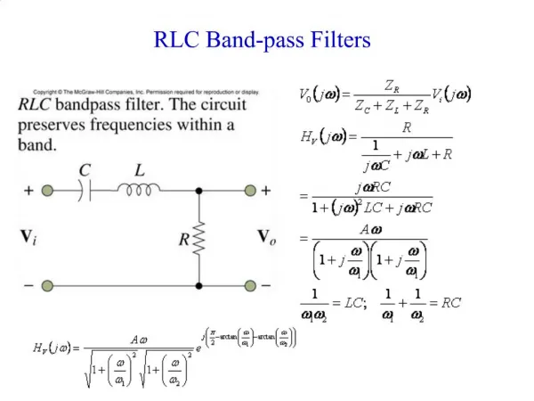
Deriving Voltage and Current from HF RFID/NFC Reader Field. Josh Wyatt Texas Instruments Embedded RF Applications/Systems Team 03/21/2011. Background.

E N D
Deriving Voltage and Current from HF RFID/NFC Reader Field Josh Wyatt Texas Instruments Embedded RF Applications/Systems Team 03/21/2011
Background • Vincent Chan (TI HK office) expressed that potential customer in his region would like to power display on transit card from High Frequency (HF, 13.56MHz) reader field using the existing tag coil and additional circuitry. • Simple circuit was designed and prototyped to demonstrate this capability. • The basic circuit concept is “textbook” and then so R and C values used could be modified to fit customer application better (if required).
Prototype Circuit Diagram Note: +3.3VDC Regulator was used here so as to not create an overvoltage condition for MSP430.
Picture of Prototype Circuit • Circuit was built using ID-1 tag coil (reference/standard size) to demonstrate operating –F2013 demo (LED blinking) from distances.
Device in Action • Using TRF796xEVM with the carrier on: • With the prototype circuit ~10cm away from the reader antenna coil, the regulator begins to output about 1.7VDC. The MSP430 is on and executing code. • @ 9cm, +3VDC is being provided and @ 8cm distance away, the full output of this particular regulator (+3.3VDC) is provided to the MSP430. • To summarize, MSP430 turns on @ 10cm out and executes the –F2013 demo code (flashing LED) from 0cm to that distance. From 10cm out, MSP430 just turned on and executing code From ~7cm out, MSP430 powered by +3.3VDC and executing code
Conclusions • Using circuit shown, but optimized to fit into card form factor it is possible to harvest sufficient energy from RFID reader carrier and reuse for powering other devices such as MSP430 to perform other tasks.