Download
1 / 22
220 likes | 266 Views
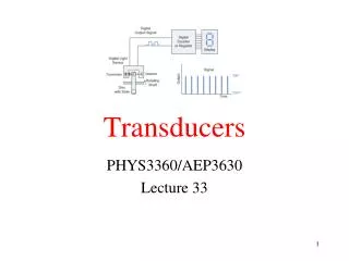
Physics of Transducers Definitions. Transducer – device that converts a signal to one physical form to different physical form Sensor – A device which converts a signal in one physical form to an electrical signal.

E N D
Physics of Transducers Definitions • Transducer – device that converts a signal to one physical form to different physical form • Sensor – A device which converts a signal in one physical form to an electrical signal. • Actuator – An output device which produces an output which displays or controls a device.
Definitions and Properties • A Transducer may be a sensor. • Sensors usually detect physical quantities which are more subtle than the human senses. • A transducer may be a sensor. • A sensor may not be a transducer. • Sensors amplify voltage. • Actuators amplify power.
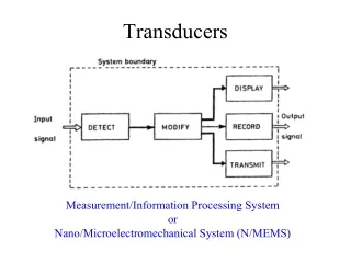
Definitions and Properties • Actuators may have either an analog or digital output. • Signal conditioning --are measuring system elements that use the output of sensors and produce an output suitable that is suitable for recording, display or transmitting. • Signal conditioning involves amplification, filtering, impedance matching, level shifting, modulation and demodulation.
Definitions and Properties • Interface – signal-modifying elements that usually change from one data domain to another. • Data Domain – a quantity used to represent or transmit information. (Fig1.2) • Analog Domain – information is carried by the amplitude of voltage, current, charge or power.
Definitions and Properties • Digital Domain – information is carried by signals having two values • Time Domain – information is carried by period, phase, pulse width or frequency. • Measurements can be either direct or indirect. Indirect example: power is measured by the product of voltage and current.
Sensor Classification • In addition to the classification of sensors by the power supply as Modulating or Self-generating. There are two other criteria • OUTPUT SIGNAL – sensors are either Analog or Digital. • OPERATION MODE – sensors are either Deflection or Null types.
General Input-Output Configuration • Let xs be the desired input signal • Let y be the output • Let xi be an interfering input signal • Let xM be a modifying input signal the modifying signal both affect the desired signal xs and xi
Compensation Techniques • The interfering and modifying inputs can be reduced by adding Negative Feedback to the measuring system. If G(s) is the transfer function between the input and output and if H(s) is the transfer function for the negative feedback, then the ratio of the output to the input is: • Y(s) = G(s)≈ __1___ • X(s) 1 + G(s) H(s) H(s)
Compensating Techniques • One can also construct the circuit with • More ideal components. Such as: low drift capacitors, low temperature coefficient resistors, etc. • Also one can put in compensating elements, such as bucking potentials, opposite temperature coefficient to the part which are changing positively.
Static CharacteristicsAccuracy, Precision and Sensitivity • Need for static calibration with standard quantities through NIST. • Any discrepancy between the accepted value and the instrument is error. • Absolute error = Experiment – Accepted • Relative error = Absolute error • Accepted Value
Static CharacteristicsAccuracy, Precision and Sensitivity • Accuracy Class – all sensors belonging to the same class have the same measurement error (in working range) • Index of class normally 1 , so error of a thermometer of 25oC +/- 1oC , likewise for • One reading 30oC. If in class 0.2 then 25oC would be 25oC +/- 0.5oC and the • 30oC +/- 0.6oC.
Static CharacteristicsAccuracy, Precision and Sensitivity • Precision –high ability to be repeatable • (agreement among different readings) • Repeatability – repeatable during short time interval with probability of 95% Reproducibility – repeatable over a long interval using different instruments in different laboratories, also assumes 95%.
Static CharacteristicsAccuracy, Precision and Sensitivity • Other parameters affecting error • Zero drift – Output drifts when input is zero • Scale factor drifts – affects sensitivity • Sensitivity (scale factor) is slope of the • calibration curve. • S(xa) = dy/dx │xa • for y = kx +b S = k (a constant)
Linearity and Resolution • Linearity – closeness between the calibration curve and a straight line. • Independent linearity – least squares fit • Zero based linearity – least squares + zero • Terminal based linearity – straight line based on minimum input and theoretical high output. • End-Points Linearity – straight line based on input zero and full scale output. • Theoretical Linearity – based on theory when designed.
Resolution and Hysteresis • Resolution – the minimal change in the input that makes a just detectable output change. • If the input starts at zero, then it is called the –Threshold. • If the sensor respond rapidly, then the noise floor (random fluctuations) determines the resolution. • Hysteresis is the difference in the output compared for the same input when the input was either increasing or decreasing
Systematic Errors • Systematic errors – Under same circumstances of measurement the same absolute value of error occurs or varies according to known measurement conditions or laws. • Discovered by measuring the same quantity using different devices or different methods or different operators.
Systematic Errors • Indirect measurements with errors that propagate, and are less accurate than direct measurements. • V = I R Direct measurement dV/V =0.1% • dV = dI + dR • So dV = dI + dR If dI = 0.1%, dR =0.1% • V I R I R • Then dV/V = 0.2%