Download
1 / 18
190 likes | 283 Views
Commissioning, operation and first physics results of the CDF Run2a Silicon and status of its future upgrade for Run2b Gino Bolla Purdue University For CDF RUN2 Silicon Group. CDF RunII (The need for a strong tracker). Physics with 2-9 fb-1 Precise Measurements of M top and M W

E N D
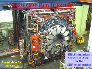
Commissioning, operation and first physics results of the CDF Run2a Silicon and status of its future upgrade for Run2b Gino Bolla Purdue University For CDF RUN2 Silicon Group
CDF RunII (The need for a strong tracker) • Physics with 2-9 fb-1 • Precise Measurements of Mtop and MW • CP violation, Bs mixing • More … • B,C quarks tagging is crucial • Long lifetime (mm to cm) • Vertex finding • High impact parameter resolution • Efficient trigger • SVT (secondary Vertex Trigger) • Fast (@L2) displaced tracks trigger. SVXII + ISL + L00 7-8 silicon layers 722000 ch rf, rz views z0max=45 cm, max=2 1.3<R<30cm COT 30240 ch, 96 layer drift chamber s(1/pT) ~ 0.1%/GeV s(hit) ~ 150mm
A top candidate • Typical travel distances: • Bottom: 5 mm • Charm: 1 mm • Impact parameter resolution • ~35 mm in F • Will improve by using L00
y [cm] x [cm] CDF Silicon (What does it look like) SVXII Use L00/SVXII for vertexing & trigger: high density & precise alignment crucial! Use ISL for tracking: simpler design; precise alignment not so important L00 ISL • 1 layer (L00) very close to the beam:improve IP res. & b-tagging • HIGHLIGHTS: • High speed • Dead-timeless operation • Displaced track trigger • 5 layers (SVXII) very compact in r,f,z: 3D vertexing & tracking • 1 central / 2 forward layers (ISL) at large radius: tracking
5 double sided layers 3 x 90o and 2 x 1.2o Very compact Tight alignment tolerances For the trigger Very symmetric Many (maybe too many) different components 6 electrical barrels Z SVXII the center piece 10.6 cm 2.5 cm x y Note “wedge” symmetry
lightweight signal & bias cables (Kapton) SVXII inner bore 2.3cm Be beampipe sensors 4.2cm cooling tube ISL on the outside and L00 on the inside • Precision position measurement before scattering • One SS layer on the Beam pipe • 25 mm pitch (50 mm readout) • Low material budget • High Radiation • Actively cooled LHC-like sensors • Electronic at larger radii L00 ISL • One central layer • Link tracks from COT to SVXII • Two forward layers (~2 m long) • Extend tracking up to |h|=2 (COT stops at 1) • Simpler design • Not used on the trigger (relaxed alignment) • Hybrids mounted OFF silicon • A single flavor • Lot of space (compared to SVXII)
Fabricated in the Honeywell 0.8mm rad.hard process 46 pipeline cells 128 channels The heart of it all (the SVX3d chip) • Analog Front End (FE) and Digital Back End (BE): • Compatible with 396/132 nsec bunch spacing • FE has relatively low noise integrator with 128 channels and 46 cell analog pipeline with 4 buffer cells • BE has comparator, 8-bit Wilkinson ADC, and sparse readout with neighbors logic • Dead-timeless: • Capable of analog operations during digitization and readout • Dynamic pedestal subtraction: • Enables on-chip common mode noise suppression
Same data but different code Integration and Commissioning A long list of troubles to deal with • Most of them specific to the CDF system • Others are of common interest A good monitoring strategy • First look at the whole thing as a piece of hardware • Second look at it as a particle detector Now 90+% is producing good data for physics Wire-bonds with current in the 100 mA range if pulsed at the right frequency can oscillate due to small (10-50 mg) Lorentz forces because resonance behaviors can be excited. Fatigue induces cracks on the heel and the electrical continuity is lost Large effort on the offline as well • Clustering • Alignment • Tracking algorithms
charge collection charge correlation z side charge [ADC] Charge [ADC] f side charge [ADC] resolution 9mm Residual [mm] Performance (1) Single hit Efficiencies~99 % dE/dx particle identification S/N >10
Performance (2) • Measurements using triggered J/Psi candidate events since January 2003 shutdown. • No background subtraction is performed. • A further 3 % increase on efficiency is expected • Performing a background subtraction (about 1%). • Improvements of ISL alignment and retuning of the the tracking road sizes (about 2 %) Average tracking Efficiency is 87.8 ± 0.1 (stat)% Average fake rate is 1.7 ± 0.4 (stat)%
Performance (3) At a higher level things get more complicated • B-tagging efficiencies in the 40-50 % • Visible degradation of performances in the regions between barrels • Will improve in the future • Adding L00 will help in between barrels • h coverage will increase by using ISL Lots of CDF physics talks at this conference
2.5 MHz 25 kHz secondary vertex 250 Hz primary vertex impact parameter 50 Hz SVT (Secondary Vertex Trigger) • Input (L1A ~10-40 KHz) • Outer drift chamber trajectories • Silicon pulse height for each channel • Output (~ 20 ms later) • Trajectories that use silicon hits • 150 VME boards • Find and fit silicon tracks with ~ offline accuracy In 15 microseconds look for 2 tracks with impact parameters > 120 mm L1: 5.5ms, synchronous, fast programmable logic (CAL, m, COT tracks) L2: ~30ms, asynchronous, programmable logic + CPU (jets, silicon tracking) L3: ~200 PCs spend ~1s/event on ~full reco (full-precision tracking, form masses, etc.) ~140 separate trigger paths (e, m, t, n, g, jet, displaced track, b-jet, …) a few mm
35mm 33mm resol beam s = 48mm 24 ms 0 10 20 30 40 50 SVT latency (ms) -500 -250 0 250 500 SVT impact parameter (mm) SVT performance +500 d (mm) vs f (raw) 0 -500 0 p 2p +500 d (mm) vs f (subtracted) 0 -500
A paper with only 12 pb-1 • Results: M(Ds) – M(D+) • 99.41 + 0.38 + 0.21 MeV/c2 • PDG: 99.2+0.5 MeV/c2
What is there ahead of us Until the LHC turn-on, the Fermilab Tevatron has the highest energy collisions and is the only place to search for the Higgs and other new particles. The Run II Physics Program extends to 5-15 fb-1. Expected life of the Run IIa Silicon detector ~ 4-5 fb-1 . Run IIb Silicon Detector replaces the inner 6 layers with an improved and radiation tolerant detector. Need to be built in a very tight schedule
The CDF Run2b Silicon Improvements in RunIIb Design: • Rad hard RO chips (0.25mm technology) • Extension of the “contained b-jets” region (active length = 1.2 m vs 0.9m in RunIIa) • larger and more uniform radial distribution (R= 2.1 – 16.4 cm compared to 1.3-10.6cm in RunIIa) • Good impact parameter resolution with low mass L0 design • Strengthened inner tracking - redundant axial layers at L1 • Larger radius outer staves - better connection to ISL • Fewer component parts: 4-chip hybrids used on 93% ofstaves Layer 0: 12 fold Axial Layer 1: 6 fold Axial-Axial Layer 2: 12 fold Axial-Stereo (1.2o) Layer 3: 18 fold Axial-Stereo (1.2o) Layer 4: 24 fold Axial-Stereo (1.2o) Layer 5: 30 fold Axial–Axial
ped+signal Laser test pedestal subtracted signal ADC Channel # Run2b Silicon Well advanced project prototype stave • the SVX4 chip works! • the stave concept works! • prototyping of most components ~finished • most parts well in time prototype barrel
Summary • The CDF silicon detector is doing its job and produces good data necessary for the physics program of the experiment • A lot of struggling during the commissioning • A well organized maintenance plan in place • The innovative Fast displaced tracks trigger is enhancing the experiment capabilities • Still work to be done to fully exploit the Si capabilities (L00 and ISL on the offline analysis) • The TeV program extends over the lifetime of the existing hardware • To fully explore the potential for new physics at CDF the RUN2b silicon is approaching its production phase.