Download
1 / 18
180 likes | 347 Views
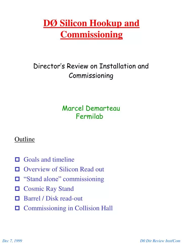
DØ Silicon Hookup and Commissioning. Goals and timeline Overview of Silicon Read out “Stand alone” commissioning Cosmic Ray Stand Barrel / Disk read-out Commissioning in Collision Hall. Director’s Review on Installation and Commissioning. Marcel Demarteau Fermilab. Outline. Goals.

E N D
DØ Silicon Hookup and Commissioning • Goals and timeline • Overview of Silicon Read out • “Stand alone” commissioning • Cosmic Ray Stand • Barrel / Disk read-out • Commissioning in Collision Hall Director’s Review on Installation and Commissioning Marcel Demarteau Fermilab Outline D0 Dir Review Inst/Com
Goals • Ensure data integrity at the level of 1014 - 1015, i.e allow for loss of 1 bit in 1014 - 1015 bits transferred • Provide adequate operating margin for device • Ensure adequate diagnostics tools and controls • Exercise control logic • Exercise Data Acquisition and filtering scheme • Exercise offline software Timeline • Commission read out electronics in phases “on the bench” without detectors attached • Integrate final components as soon as available • Read out small scale setup in final configuration • Enlarge scope of read out D0 Dir Review Inst/Com
Current Status • Complete read out system installed in cleanroom in LabC • Final version of all read out components, except Interface Board • System run in checksum mode in Level 3 node • SVX chips downloaded to read out set data value • All channels read out; data constant • Calculate checksum (sum of all bits) in VBD • Data transferred to L3 node; checksum compared • If checksum different: read in and analyze even D0 Dir Review Inst/Com
A)Ran with multiple VME Read out Buffer (VRB) boards, without low mass cable and long transmission line, with direct regeneration of signals at hdi, 3-chip hdi’s only System equivalent of ~22,000 channels Data transfer on VME at ~ 12 Mbytes/s • Very low noise on data transfer backplane • Proper handshaking between read out elements • Data integrity > 1013 (~ 1 non-fatal error every ~30 minutes) B)Ran with single chain (hdi) in close to final configuration, including low mass cable, 30’ 3M/50 conductor cable. Optimized impedance matching for data and control lines on sending and receiving ends • Successfully operated all hdi types • Mapped out operating margin for all hdi types • Data integrity > 1013 for all hdi types with comfortable operating margin C)Written raw data to disk, unpacked and analyzed “offline” within L3 framework and online monitoring program (Examine) D0 Dir Review Inst/Com
DØ - D7 Data bus lines DValid Clock strobe Read out at 53 MHz Strobe channel id Strobe data 18.8 ns Bus lines D0/D7 WCLK and DVALID signal risetime of 2-3 ns Upper limits 7-8 ns Operating Margin D0 Dir Review Inst/Com
Schedule and Resources • 12/05/99: Expand to 6 chains with low mass configuration • 12/15/99: Implement new interface board • 50 80 conductor cable with SVX power provided through cable • monitoring capabilities added Verification of data acquisition and data integrity will be ongoing effort D0 Dir Review Inst/Com
Cosmic Ray Setup • Install up to 12 ladders in spare Be support structure and exercise full read out system, DAQ, L3 and on/offline software, controls and monitoring • First step in trying to operate full barrel disk Array of 4 scintillator counters form external trigger Momentum analyzing steel, pT > 2 GeV/c Data Rate ~ 1 cosmic/min Ladder installation in progress D0 Dir Review Inst/Com
Setup • 6 ladders read out through low mass cable in final configuration • 6 ladders read out through high mass cable: Total of 9216 channels • Barrels will be cooled and interlocked • First cosmic ray recorded 12/20/99 Ingredients • Detector Control and Monitoring • Secondary Data Path • Data Acquisition • Online data monitoring (Examine) D0 Dir Review Inst/Com
EPICS DB Generator ORACLE Hardware Database Detector Controls and Monitoring All slow controls and monitoring uses 1553 protocol 1553 interface to Si detector only available with new Int.Brd. 1553 Detector Controls • Download of Sequencer and SVX chips, not optimized • SVX and bias Voltage control done, need implementation Controls Crate Readout Crate Ethernet EPICS Clients: SVX Download Low Voltage High Voltage 1553 Devices Rack Monitor Control Room PCs UNIX Hosts Available In progress • 1553 Monitoring devices, currents, temperatures • Cooling monitoring and interlock • Oracle database design population and interface D0 Dir Review Inst/Com
Detector Motorola 68k or Power PC Pwr PC Readout Crate Ethernet PTP Connection Host Processor: Calibration ORACLE Hardware Database Secondary Data Path Intended for calibration processes and monitoring For Silicon: calculation of pedestals and gains • Front-End software finished as stand alone L3 Node Available In Progress • Porting to cosmic ray setup Jan 00 • Exercise system Feb 00 • Database interface first pass March 00 • Database retrieval April 00 D0 Dir Review Inst/Com
Oracle Database Run Configuration Readout Configuration Monitoring Devices • Module addressing and read out • chip id, pedestal, gain, ladder barrel, Temp address, I address Geometry parameters Control Parameters Calibration Constants D0 Dir Review Inst/Com
Detector Trigger and Readout Readout Crate L1/2 Trig Simul Data Cable L3 VRC L3 Supervisor Data Cable L3 Filter NT Level 3 Ethernet Collector / Router Data Distributor Data Logger Examine Disk UNIX Hosts Control Room PCs Data Acquisition • All pieces to exercise full data acquisition chain are in place • Read out to L3 system extensively tested • Online Examine SMT analysis code tested on raw data • First pass at full read out with 12 ladder test Dec 99/Jan 00 • Will slowly ramp up to enlarge read out and complexity of tools • L3 Tools: data unpacking, hit finding, track reconstruction D0 Dir Review Inst/Com
Timeline for development • Dec 99: • 6-12 ladder setup and test controls and monitoring • Dec 99 - Jan 00: • Cosmic Ray data taking; online monitoring with Examine • Feb 00: • First pass at L3 filtering and alignment • First pass at secondary data path • Mar 00: • Database integration D0 Dir Review Inst/Com
Timeline So far discussed development on small scale system (12 ladders) and commissioning of read out system. Move to full subsystem in March 00. • March 15/00: • Hook up of full H-disk, 48 detectors, 36864 channels; exercise all components • April 1/00: • Hook up barrel, 72 detectors • April 15/00: • Hook up barrel and F disk, 96 detectors (~10%) • May 1/00: • 15 more detector assemblies to go (5 barrel/disk, 6 F disks, 1+3 H disks) • one week for read out and debugging per assembly • Done Aug 15/00 • Note, doubling the time per assembly (23 assemblies) would give completion date of Oct 7/00. Still adequate (7 H disk assemblies can go last) No assembly (barrel or disk) leaves the silicon facility without having been read out. D0 Dir Review Inst/Com
SEQ SEQ SEQ platform Meanwhile in the Pit SVX EMULATOR Monitoring Control 3/6/8/9 Chips 3M Low Mass IB Optical Link 1Gb/s Sensor NRZ / CLK 1 5 5 3 VRB VRB VRB VRB VBD 68k VME VRB Controller L3 HOST Secondary Datapath Examine Concurrent with work at the silicon facility, a complete shake down of the read out system will take place at the assembly hall of final read out configuration downstream from the interface board, including online data checking (Examine). See M. Johnsons presentation D0 Dir Review Inst/Com
Barrel and disk hookup at DAB • Hookup of cooling system immediately • Run coolant above dewpoint, so no damage to detectors. Procedure verified at silicon facility • Starting 9/26/00, 5 weeks allocated for check out of silicon detector • 1.5 weeks allocated for cabling each detector end. Note, read out has HDI-enable line, therefore, system can be fully powered at hookup time, thus instant hdi checkout.Procedure should be developed at silicon facility during full barrel/disk tests • Complete Barrel and F disk hookup in 3 weeks. • Assuming 7days/week, 12hrs/day, this gives ~20 mins of debugging time per hdi • Two additional weeks for debugging complete barrel and F disk assembly. Hookup of H disks in parallel. D0 Dir Review Inst/Com
Resources D0 Dir Review Inst/Com
Summary • Read out system will be verified continuously. Current level of data integrity for single hdi would be adequate. • Partial barrel with cosmic ray data taking first step to final system configuration • All system components will be exercised at the silicon facility and procedures developed for DAB hookup and commissioning • Many DAQ components exist already in stand alone form, but are not integrated. • All full assemblies will have been read out at the silicon facility before installation. Development of procedures at facility crucial. • Schedule is tight but feasible D0 Dir Review Inst/Com