Download
1 / 44
460 likes | 815 Views
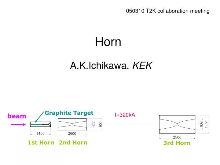
Graphite Target. beam. 1st Horn. 2nd Horn. 3rd Horn. 050310 T2K collaboration meeting. Horn. A.K.Ichikawa, KEK. I=320kA. Activity around Horns. Japanese construction group Target design : T. Nakadaira et. Al S. Hatakeyama (stripline insulation)

E N D
Graphite Target beam 1st Horn 2nd Horn 3rd Horn 050310 T2K collaboration meeting Horn A.K.Ichikawa, KEK I=320kA
Activity around Horns • Japanese construction group • Target design : T. Nakadaira et. Al • S. Hatakeyama (stripline insulation) • Y.Hayato (3rd horn inner conductor) • S. Koike (support structure) • T.Nakadaira (3rd horn inner conductor) • H. Sato (cooling test, 1st horn outer conductor) • S. Tada (support structure) • Y. Yamada (support structure) • International collaboration • US( Colorado ) (E.Zimmerman, L.Bartoszek) • Start working on design and beam MC.
New plots and numbers based on the 04b flux • Notice: • Primary proton energy is 40 GeV since that value is planed for the 1st phase of the J-PARC accelerator. • The number of interaction at Super-K is decreased from the LOI number because • Smaller beam power at 40 GeV with same assumption on POT. • Smaller cross section for OAB2.5deg than OAB2.0deg. • ne contamination is increased due to the longer decay volume(~130m) than the LOI assumption (~80m) • Still sensitivity plot is not updated.
Super-K. q Decay Pipe Target Horns Off Axis Beam (ref.: BNL-E889 Proposal) • Quasi Monochromatic Beam • x 2~3 intense than NBB Tuned at oscillation maximum Statistics at SK (OAB 2.5 deg,1 yr,22.5 kt) ~ 2200nmtot ~ 1600nmCC ne~0.4% atnmpeak OA0° OA2° OA2.5° OA3° Neutrino energy spectrum sxF (Note )
Flux OAB2.5deg, Ep=40GeV nm ne
Near/Far ratio Flux at SK Flux at ND Flux at SK Flux at ND at 2km at 280m
Event rate at ND280mper 1021POT Y. Hayato detector area(cm^2) nu mu nu_e ND2 300 x 300 1.08e+06 9.32e+03 events/ton = 0.35/spill/ton ND3 1000 x 100 8.83e+05 8.38e+03 events/ton ND4 100 x 1000 9.00e+05 8.44e+03 events/ton ND5 300 x 300 1.70e+05 3.34e+03 events/ton =0.056/spill/ton ND6 300 x 800 1.82e+05 3.31e+03 events/ton On-axis OAB2.5deg
Optimization of inner-conductor shape based on stress analysis • Stress due to Lorenz force and heat load have been examined by FEM. • 1st horn : Optimization by static analysis and confirmation by dynamical analysis already done • 2nd horn : First version by static analysis • 3rd horn : Optimization by static analysis • This time, confirmation by dinamical analysis done. s=18MPa (c.f. allowable= 25MPa)
1st Horn-design and prototype production- Big contribution to the design from US group (Colorado univ., Bartoszek Engineering)
Prototype production Inner conductor
Prototype production Outer conductor Made from a forged block! Nozzle port Service port Fixing port
ElectroMagnetic analysis by FEM (A/m2) Current Density 18/23
(A/m2) (A/m2) Current Density 20/23
(A/m2) (A/m2) (a)View1 (b)View2 Current Density 22/23
(A/m2) (A/m2) (a)View1 (b)View2 Current Density 23/23
(T) Magnetic Flux Density 15/23
Next FY plan-1st horn- • Design and production of remaining items • Current feeder shape based on the electromagnetic analysis • Cooling pipe configuration • Fixation • etc. etc…. • Test operation • 250kA at first • Cooling test • Field measurement • 250kA endurance test • etc.etc…
3rd Horn Inner-conductor-design and prototype production- Now being manufactured. It will arrive soon,
Next FY plan-3rd horn- • Design and production of remaining items • Outer Conductor • Insulator ring • Current feeder shape based on the electromagnetic analysis • Cooling pipe configuration • Fixation • etc. etc….
Target Area Service pit Helium vessel Transformer Concrete shield (1m) Bus bar Iron Shield (2.2m) Pions into Decay Volume Iron shield 3rd horn 2nd horn Target in 1st Horn Collimator Proton beam Iron structure Concrete structure
Very conceptual design Iron box Distortion~200mm ~1.5mくらいか ~4m Supporting point ~1m Achieve 1mm accuracy at the horn with ~300mm alignment at the supporting point
1st horn w/ Support structure Drawn by S. Koike
Dock of horns Do positional alignment between a horn and support structure at the Target Station ground floor. Baffle target and 1st horn 2nd horn 3rd horn http://jnusrv01.kek.jp/~ichikawa/jhfnu/tgt-horn/support/TSsupport.040927.ichikawa.dwg
Maintenance scenario (not official) • Target + 1st horn : exchange once per 2 years at most • 2nd horn : exchange once per 4 years • 3rd horn : exchange once per 4 years • Baffle : exchange once per 5 years • Requirement • Reproduce with 1mm accuracy • To save the waste stock room, it is desired that the equipment and support structure can be disconnected (remotely of course). • To save the waste stock room more, and to save the operation cost, it is preferred that the support structure is re-usable. • Remote disconnection/connection of horn stage, strip-line, water pipe, He pipe.
NuMI horn 外国の研究所では、 Remote stripline clamp test How to hook and unhook horn from power stripline remotely in radiation area? Shaft toggles clamp to provide pressure for good electrical connection Contact surfaces fine after two plug/unplug cycles 1.8 million pulses total
支持機構の着脱 –吊り下げロッド- 支持機構箱に固定 ステンレス? このような吊り下げロッドで、4箇所から吊り下げる。 1本にかかる荷重は、最大200kg程度。 ジャッキで引き上げる? 吊り下げロッド アルミニウム? 回転してホーン台支え棒を引っ掛ける ホーン台支え棒 高さ位置決め
位置決めロッド 支持機構側 1番目 2番目 水平方向位置決め ホーン台の2箇所につける。 1番目 : 水平両方向 2番目: 水平一方向
吊り下げロッド ここら辺と反対側に位置決めロッド
R&D work for each component will be done in next FY. There are many rooms for contribution from outside KEK. Contact either Kobayashi-san, Yamada-san or me.
Schedule of FY2005 August 1st Horn Design&Production Test Operation 3rd Horn Design Production Stripline R&D Support structure