Download
1 / 32
330 likes | 537 Views
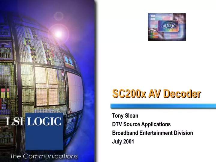
SC200x AV Decoder. Tony Sloan DTV Source Applications Broadband Entertainment Division July 2001. SC200x AV Decoder Overview. Overview MPEG2 AV Decoder has the following modules I-Bus Interface (to Host CPU) S-Bus Interface (to SDRAM-B) DMA Controller AV Decoder Interface

E N D
SC200x AV Decoder Tony Sloan DTV Source Applications Broadband Entertainment Division July 2001
SC200x AV Decoder Overview • Overview • MPEG2 AV Decoder has the following modules • I-Bus Interface (to Host CPU) • S-Bus Interface (to SDRAM-B) • DMA Controller • AV Decoder Interface • AV Decoder Core • SDRAM Interface (to SDRAM-A) • Audio DAC
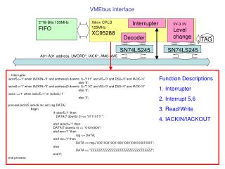
S-BUS To SDRAM-B I-BUS To TinyRISC CPU Subsystem I-Bus Interface DMA Controller Host Interface Digital Out L64105 Core AudioDAC CPU Interface A/V Decoder Analog Out PES FromTransportSubsystem ChannelInterface MemoryInterface S/P DIF Out To Video Mixer/Encoder Digital Out SDRAM-A SC200x AV Decoder Block Diagram
AV Decoder I-Bus Interface Features • I-Bus Interface • Features • Interface between the CPU and the AV Decoder • Used to configure the AV Decoder • Divided into four sub-areas • General Registers • DMA Controller Registers • AV Decoder Core Registers • Audio DAC Registers • 32 bit wide Data and Address Bus • The bottom 8 bits of Data Bus used, top 24 bits are reserved
I-Bus Interface Registers • I-Bus Interface • General Registers • Version, Software Reset, Interrupt Enables, Interrupt Status • Address range 0xbe40.000 to 0xbe40.ffff • DMA Controller Registers • CPU SDRAM Start Address • AV Decoder SDRAM Start Address • Number of Bytes to transfer • DMA Control Register • Address range 0xbe41.000 to 0xbe41.ffff
I-Bus Interface Registers • I-Bus Interface • AV Decoder Core Registers • Same register set as for the L64105 but on 32 bit boundaries • Address range 0xbe42.000 to 0xbe42.077c • Audio DAC Registers • PCM Configuration, Mute mode, Filter mode • Configuration A (sample rate select, soft mute) • Configuration B ( half sample rate,LR clock invert) • Volume Control • Status • Address range 0xbe42.0780 to 0xbe42.0798
AV Decoder Register Summary A/V Decoder Register Summary Register Group Start Address End Address L64105 Group I-Bus Interface Registers 0xbe40.0000 0xbe40.ffff New DMA Controller Registers 0xbe41.0000 0xbe41.ffff New A/V Decoder Registers 0xbe42.0000 0xbe42.ffff All (0-511)(now includes ADAC) CPU Interface Registers 0xbe42.0000 0xbe40.00ff 0-63 Video Decoder Registers 0xbe42.0100 0xbe42.02ff 64-191 Memory Interface Registers 0xbe42.0300 0xbe42.037f 192-223 Microcontroller registers 0xbe42.0380 0xbe42.03ff 224-255 Video Interface Registers 0xbe42.0400 0xbe42.053f 256-335 Audio Decoder Registers 0xbe42.0540 0xbe42.05ff 336-383 Ram Test Registers 0xbe42.0600 0xbe42.0620 384-392 Reserved 0xbe42.0624 0xbe42.077c 393-479 Audio DAC Registers 0xbe42.0780 0xbe42.0798 480-511 Reserved 0xbe42.079c 0xbe42.ffff New Unused (reserved) 0xbe43.0000 0xbe43.ffff New
AV Decoder S-Bus Interface • S-Bus Interface • Features • Interface between the CPU SDRAM and the AV Decoder SDRAM • Data transfer interface under DMA control • 32 bit wide Data and Address Bus
AV Decoder DMA Controller • DMA Controller • Features two operating modes • Standard DMA Mode • Uses the functionality in the AV Decoder Core to transfer data between the CPU SDRAM and the AV Decoder SDRAM • DMA Bypass Mode • Uses the bypass functionality in the AV Decoder Core to transfer data from the CPU SDRAM directly into the Audio or Video Channels of the AV Decoder SDRAM • Example - DMA Bypass of Still Images into the Video channel whilst playing live audio and DMA Bypass of Audio Clips whilst playing live video
DMA Controller Reads • DMA Controller • Read Operation • Ensure DMA Controller is idle • Set up the CPU SDRAM Target Address • Set up the AV Decoder Source Address • Set up the number of bytes to be transferred • Write to the DDMAC Register to set the DMAC to run • The DMA routine can be aborted by clearing the ‘run’ bit
DMA Controller Writes • DMA Controller • Write Operation • Ensure DMA Controller is idle • Set up the CPU SDRAM Source Address • Set up the AV Decoder Target Address • Set up the number of bytes to be transferred • Write to the DDMAC Register to set the DMAC to run • The DMA routine can be aborted by clearing the ‘run’ bit
AV Decoder Interface • AV Decoder Host Interface • Features • Converts the Host Interface on the L64105 core to a dual I-Bus interface • One I-Bus is connected to the DMA Controller • The second is connected to the CPU I-Bus (I-Bus Muxer) • Operation • Passes AV Decoder Register configurations from/to the CPU • Sends/receives DMA Controller data through the AV Decoder Core to the SDRAM • Accesses made from the CPU I-Bus Interface (I-Bus Muxer) have the higher priority
AV Decoder Core • AV Decoder Core • Features • The L64105 AV Decoder Core with several enhancements including variable scaling, PCM audio mix and Ancillary Data Extraction • MPEG-2 System Layer Decoding of Pack and PES Layer • MPEG-2 MP@ML Video Decoding • Concealment Motion Vectors, 3:2 Pull Down, Pan and Scan • MPEG-1 Layer I and II (MUSICAM) Audio Decoding • Audio Decode Rate Control support for low Sampling Frequencies
AV Decoder Core Block Diagram • AV Decoder Core Block Diagram
AV Decoder Channel Interface • AV Decoder Channel Interface • MPEG-2 System Layer Decoding of Pack and PES Layer
Video Decoder • Video Decoder • Video Decoding to ISO13818-2 MP@ML and to ISO11172 including the MPEG-1 System Layer
Video Decoder Interface • Video Decoder Interface • Provides an ITU-R BT.656 digital video output • Programmable Display Management available • Display Timebase Generator is slaved to the Mixer
Variable Horizontal Scaling • Horizontal Scaling • 1/4 to x4 Scaling with no additional processing required by software (after set up) • Scaling selected by writing to DMHFSFL Register (0xbe42.07ac) • and by writing to bits [2:0] of DHVFSFH Register (0xbe42.07b0) • Enable the new Display Mode (0xc or 0xd) in the DDM Register.
Variable Vertical Scaling • Vertical Scaling • 1/4 to x4 Vertical Scaling which does require additional processing by software ( for 1/4 to 1/2 scale) • Scaling selected by writing to DMVFSFL Register (0xbe42.07a8) • and by writing to bits [5:3] of DHVFSFH Register (0xbe42.07b0) • Needs 32MBit of SDRAM • Reduced Memory Mode must not be set • Four Frame Decode recommended • Software Interaction required to perform Single Step Decoding • Required to update Framestore addresses and Display Override • 1/4 to 1/2 Scaling is achieved by dropping lines and then performing 1/2 to x1 Scaling
Vertical Scaling Issue • Vertical Scaling Timing considerations • Time taken to read Display Video from Framestore • Is shorter than usual with respect to Decode time • Requires both Fields to be displayed in a shorter time • A big timing problem if image is situated at the top of the screen • Problems such as ‘tearing’ or even corruption to right of image • Not such a big problem at the bottom of the screen • Time taken to Decode Video and place in Framestore • Varies with picture content • Therefore there are too many unknowns • So Software has to take complete control of Framestores to guarantee no problems with timing
Four Frame Decode • Storage for Decoding and Display Images • Software control of Decoding • Software control of Display
Audio Decoder • Audio Decoder • Audio Decoding to ISO13818-2 Layers I and II • Supports bit rates from 8K to 448Kbits per second • Supports Sample rates of 16K,22.05K,24K,32K,44.1K and 48KHz • Outputs a Serial PCM stream to the Audio DAC • Outputs an IEC958 (SPDIF) stream externally
Audio Decoder Block Diagram • Audio Decoder Block Diagram • Audio Decoding to ISO13818-2 Layers I and II
Audio Decoder SPDIF I/F • Audio Decoder SPDIF Interface • Outputs an IEC958 (SPDIF) stream externally
Audio Decoder Interface • Audio Decoder Interface • Features • CD Bypass input for DVD Applications • An external SDPIF input • A single ACLK input (required if an external ADAC is used) • A separate low jitter clock (OCLK) is required for the ADAC output stages • OCLK and SYSCLK are typically tied together • Separate analog supply voltages are required for the resident ADAC and ADAC output stages
AV Decoder SDRAM Interface • SDRAM Interface • Features • 16 bits wide Data Bus operating at 81MHz • Interfaces to 16MBit SDRAM • Interfaces to 64MBit SDRAM * • *Only 32MBits are accessible • Operation • Conventional SDRAM Interface • Synchronous Data, Address and control lines • Programmable Refresh rates
Audio DAC • Audio DAC • Features • Resident JDA1 Audio DAC • 20 bit Sigma Delta DAC • Integral PLL produces the over-sampling clock at 256fs • Sample rates of 16K,22,05K,24K,32K,44.1K and 48KHz • 32 bit wide Registers configure Word Length, Mute Mode, Sample Clock, DAC Filter Mode and Volume Control • Address range is 0xbe42.0780 to 0xbe42.0798 • External Low Pass Filter required
Audio DAC Block Diagram • Audio DAC Block Diagram
Audio DAC Functional Specification • Audio DAC Functional Specification • Figures measured from a DAC Test Chip not SC2000 • Frequency Response (20Hz to 20KHz) DAC only <+/- 0.005dB • Frequency Response (20Hz to 20KHz) with filter <+/- 0.125dB • L/R Amplitude imbalance (20Hz to 20KHz) < 0.1dB • L/R Phase imbalance (20Hz to 20KHz) < 0.5 degree • THD+N for Full scale (1KHZ input) < 0.004% • THD+N for -60dBFS (1KHz input at -60dB) < -36dB • IMD Distortion (CCIF 4000 and 4080Hz) < 0.003%
Audio DAC Functional Specification • Audio DAC Functional Specification • Figures measured from a DAC Test Chip not SC2000 • Idle Noise - non muted (A-wghtd or CCIR/ARM wghtd) -100dB • Linearity Error (at -100dB input - 18bits) < 1dB • Crosstalk between channels (1KHz input) < 110dB • Crosstalk between channels (20KHz input) < 90dB • Dynamic Range [SNR] (Flat, 20KHz bandwidth) = 98dB • SNR variation with Fs (32KHz, 44.1KHz or 48KHz) < 1dB
ADAC Low Pass Filter • Recommended Low Pass Filter (for 3V3 operation) • Left Channel only shown
SC200x AV Decoder • End Of Presentation