Download
1 / 31
360 likes | 1.02k Views
Decoder. Mano Section 4.9 &4.12. Schedule. Outline. Feedback Applications Memory Decoder Verilog Modeling. Feedback on the labs. Tutorial emacs /vi tutorial at the course webpage. Verilog tutorial

E N D
Decoder Mano Section 4.9 &4.12
Outline • Feedback • Applications • Memory • Decoder • Verilog Modeling
Feedback on the labs • Tutorial • emacs/vi tutorial at the course webpage. • Verilog tutorial • Always start from the textbook (There is usually a section on Verilog at the end of each chapter) • Supplement the textbook with the tutorial from ASIC. • Use the existing sample code as a starting point. • Finish the labs before you leave.
Example (2): Binary to Octal Conversion Convert binary information from n input lines to 2n unique output lines. This particular circuit take a binary number and convert it to an octal number.
AND and NOR Decoders Each is a combination leading to a “1” Take an n-bit address. Produce 2n outputs, One of which is activated. (NOR Decoder)
A 2-to-4 decoder with Enable (typo, should be a 0)
Example (4): Demultiplexer A Demux is a circuit that receives information from a single line and directs it to one of 2n possible output lines.
Use a 2-to-4 decoder as a Demux Treat A and B as the selector bits. i.e. A and B select which bit should receive informraiton. E is treated as the data line. (typo, should be a 0)
Example (6): Build a Bigger Decoders Use w to enable either top or bottom decoder.
Outline • 2-to-4 decoder • Decode24a.v: uses assign statements • 3-to-8 decoder • Build from a two 2-to-4 decoder
A 2-to-4 decoder with Enable Program body: D0=~((~A)&(~B)&(~E)) D1=~((~A)&(B)&(~E)) D2=~((A)&(~B)&(~E)) D3=~((A)&(B)&(~E)) Inputs: A,B, E Outputs: D0, D1, D2, D3 (typo, should be a 0)
decode24a.v wire is declared in a more “compact” way. Instead of D0,D1,D2,D3.
Decode24a_tb.v Start from full_adder_tb.v Print out D as a 4 bit number.
3-to-8 decoder in verilog Module: decode38a.v Inputs: x,y,w wires: x,y,w outputs: D0 to D7 wires:D0 to D7 wire: wb Program body: call on two instances of decode24a I1 wb I2
3-to-8 decoder in verilog I1 wb I2
3-to-8 decoder in verilog I1 wb I2
Basic SRAM and VTC A wordline is used to select the cell Bitlines are used to perform read and write operations on the cell
Cross Coupled Configuration The cell can only flip its internal state when one of its internal cross VS. During a read op, we must not disturb its current state. During a write op, we must force the internal voltage to swing past VS to change a state.
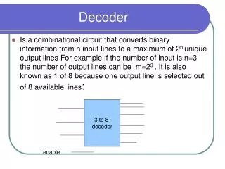
3-to-8 decode Input bits
Use a Test Bench to Generate output Initial statements execute once starting from time 0. $monitor: display variable whenever a value changes. $time display the simulation time