Download

1 / 36
440 likes | 716 Views
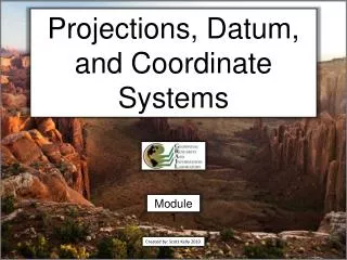
Map Projections and Coordinate Systems. Surveying 101 for GIS Professionals 2013 Kentucky GIS Conference Jeremy Gould – Kentucky Transportation Cabinet. Agenda. Geographic Coordinate Systems Ellipsoids Geoid Horizontal Datums Projected Coordinate Systems Project Datum Factors

E N D
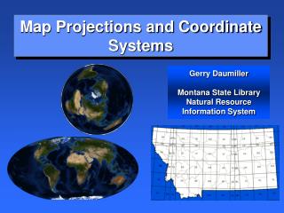
Map Projections and Coordinate Systems Surveying 101 for GIS Professionals 2013 Kentucky GIS Conference Jeremy Gould – Kentucky Transportation Cabinet
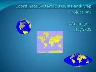
Agenda • Geographic Coordinate Systems • Ellipsoids • Geoid • Horizontal Datums • Projected Coordinate Systems • Project Datum Factors • Vertical Datums
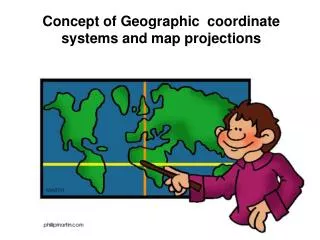
Geographic Coordinate Systems • Geographic Coordinates Systems use radial coordinates to locate a point on a specifically defined sphere (ellipse). These are called spherical coordinates. Cartesian point P can also be represented in spherical coordinates (λ,φ, γ) where: λ= +/- degrees longitude Φ= +/-degrees latitude γ= + radial distance from center
Geographic Coordinate Systems Kentucky (-85.3 °,37.5 °) (85.3 ° W, 37.5 ° N) Equator 0° latitude Prime Meridian 0° longitude
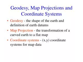
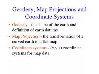
Ellipsoids • Ellipsoids are flattened spheroids that when referenced to the earth can be rotated and/or shifted to best fit the earth (geoid) either in part or in whole
Geoid • The geoid is an equipotential gravimetric surface resulting in an irregular and non-mathematical approximation of the earth’s size and shape relative to a base of reference that best fits global mean sea level in a least squares sense • The geoid is a 3 dimensional surface along which the pull of gravity is a specified constant • The geoid is a measured and interpolated surface and not a mathematically defined surface • Differences in the density of the Earth cause variation in the strength of the gravitational pull, in turn causing regions to dip or bulge above or below the reference ellipsoid
Geoid Gravity Recovery And Climate Experiment (GRACE)Gravimeters
Ellipsoids There are Global Ellipsoids and Regional (local) Ellipsoids Two Global ellipsoids are GRS80 and WGS84
Horizontal Datums • A datum is a reference surface • A geodetic datum consists of two major components • Ellipsoid with a spherical coordinate system and origin • Set of points and lines that have been surveyed • A geodetic datum is a three dimensional Euclidian reference frame defined relative to an associated ellipsoid oriented to achieve a best fit statistical approximation of the geoid either in part or in whole. • The North American Datum (NAD) has been defined by two different ellipsoids, the Clarke ellipsoid of 1866, which was oriented to best fit the North American continent and is the basis of NAD27, and the Global Reference System ellipsoid of 1980 (GRS80) which is a globally defined ellipsoid and the basis of NAD83.
CLARKE 1866 Ellipsoid (NAD’27) GRS80 Ellipsoid (NAD’83) Earth MassCenter Approximately236 meters GEOID Ellipsoid, Geoid, and Datum
Horizontal Datums • Lat and Long locations of given benchmarks in the NAD27 datum will likely be different from the lat and long of that same benchmark in the NAD83 or WGS84 datum's. • The monumented points do not move • This is described as a datum shift • Shift in coordinate locations from WGS84 to NAD83 is often less than 1 meter • Datum shifts between NAD27 and NAD83 are often 100’s of meters
Horizontal Datums • Geographic Position (Lat-Long) (variations between datums for same position) Example: Datum 1 may have a long-lat of (-85.31 °, 37.55 °) Datum 2 may have a long-lat of (-85.30 °, 37.54 °) The same point has different coordinates because of the shift/rotation of the ellipsoid
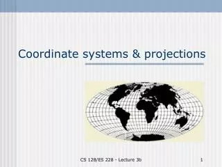
Projected Coordinate Systems • A mapping projection is a geometric tool that allows a portion of a spherical surface to be represented on a two dimensional surface such as a flat sheet of paper or computer screen in a spatially consistent manner. • A State Plane Coordinate System is a specialized mapping projection that allows direct conversion between spherical geographic coordinates of latitude () and longitude (), and rectangular Cartesian coordinates of northing (y) and easting (x).
Projected Coordinate Systems • So how do we get from our Geographic Coordinates to a Projected Coordinate System?
Projected Coordinate Systems Cylindrical Conical Planar
Projected Coordinate Systems • Transverse Mercator Projection SF < 1 Practical Limit of Projection (SF k0) SF > 1 Axis of Cylinder Grid Origin Intersection of Ellipsoid and Projection Cylinder (SF = 1) Central Meridian (SF = k0) Polar Axis
Projected Coordinate Systems KENTUCKY PROJECTIONSUTM Zones 16 & 17Transverse Mercator (Secant Cylinder) UTM Zone 17 UTM Zone 16
Projected Coordinate Systems • Lambert Conic Projection (Northern Hemisphere) North StandardParallel (SF = 1) Polar Axis Central Meridian South StandardParallel (SF = 1) Parallel ofGrid Origin(Base Parallel)
State Plane Coordinate Systems • State Plane zones are sometimes identified by the Federal Information Processing System (FIPS) Codes as shown below
State PlaneNorth Zone State Plane South Zone Projected Coordinate Systems KENTUCKY PROJECTIONSNorth and South State PlaneLambert Conformal Conic (Secant Cone)
Projected Coordinate Systems KENTUCKY SINGLE ZONE PROJECTION
Projected Coordinate Systems KENTUCKY SPCS – NORTH AND SOUTH ZONES NORTH ZONE SOUTH ZONE
Projected Coordinate Systems Kentucky ProjectionsNAD83 State Plane Coordinate System(Lambert Conformal Conic) Linear unit of measure for all zones is the U.S. Survey Foot (USFt) (1 USFt = .3048006096012 meters)
Projected Coordinate Systems COORDINATE SPACE COMPARISON 1,500,000 m 4921245 ft 1,250,000m 4101038 ft NAD'83 SINGLE ZONE 1,000,000 m 328083 ft NORTHING 750,000 m 2460623 ft NAD'83 SOUTH ZONE 500,000 m 1640415 ft NAD'83 NORTH ZONE 250,000 m 820207 ft NAD'27 NORTH ZONE NAD'27 SOUTH ZONE 0 m 0 ft 0 m 0 ft 820207 ft 250,000 m 500,000 m 750,000 m 328083 ft 5741453 ft 1640415 ft 6561660 ft 4921245 ft 2460623 ft 4101038 ft 1,000,000 m 1,250,000 m 1,500,000 m 1,750,000 m 2,000,000 m EASTING
E1 < G1 < S1 S1 E = Distance on ellipsoidG = Distance on gridS = Distance on surface SF = Grid Scale Factor = Geodetic latitude G1 G2 < E2 < S2 S2 E1 E2 SF>1 Ellipsoid SF=1 G2 Topographic Surface(Ground) SF<1 Axis of Rotation North Standard Parallel Projection Grid E3 < S3 < G3 SF=1 G3 South Standard Parallel S3 SF>1 E3 Equatorial Plane Projected Coordinate Systems
Project Datum Factor • A Project Datum Factor (PDF) converts grid distances (state plane coordinates) to ground/surface distances. • If you were to use a total station to measure distance between two points on the ground and then used GPS to measure the location of the same two points and calculate the distance between those two points on the state plane grid, the two distances would be close but not exactly the same. This is due to the curvature of the earth combined with the elevation above sea level of the project location. The grid (state plane projection) is trying to represent the elevated, curved surface of the earth on a flat plane at sea level. • The PDF was more prevalent before GPS became popular because total stations were the primary tools used for surveying. • Projects were designed using the PDF. This allowed surveyors in the field to measure directly from the designed plans, without having to apply the PDF on the fly in the field.
Project Datum Factor Example 0’s Inverse of PDF 1/1.000059148
Conversion Among Coordinate Systems • Exact or approximate mathematical formulas have been developed to convert to and from geographic coordinates (lat and long) to all commonly used coordinate projections • Care must be taken when converting among projections that use different datums • A datum transformation must be used to convert from one geographic coordinate system to another
Conversion Among Coordinate Systems Inverse of PDF Inverse of PDF
Vertical Datums • Many Vertical Datums • GPS provides Elipsoid height
Summary • Geographic Coordinate Systems • Ellipsoids • Geoid • Horizontal Datums • Projected Coordinate Systems • Project Datum Factors
References • http://kartoweb.itc.nl/geometrics/index.html • http://resources.arcgis.com/en/help/main/10.1/index.html#//003r00000001000000 • http://training.esri.com/gateway/index.cfm?fa=catalog.webCourseDetail&courseid=24 • http://transportation.ky.gov/Highway-Design/Pages/Survey-Coordination.aspx • http://www.agc.army.mil/Missions/Corpscon.aspx • Basic GIS Coordinates, Second Edition: Jan Van Sickle • http://www.esri.com/news/arcuser/0703/geoid1of3.html
Questions? Hopefully after this talk your project won’t look like this.