Download
1 / 19
250 likes | 513 Views
Dynamic Voltage and Frequency Scaling Circuits with Two Supply Voltages. ECE Department, University of California, Davis. Wayne H. Cheng and Bevan M. Baas. Outline. Background and Motivation Implementation Results. DVFS Background. P dyn = α CVdd 2 f E = CVdd 2 t d ≈ CVdd/(Vdd−Vt) α.

E N D
Dynamic Voltage and Frequency Scaling Circuits with Two Supply Voltages ECE Department, University of California, Davis Wayne H. Cheng and Bevan M. Baas
Outline • Background and Motivation • Implementation • Results
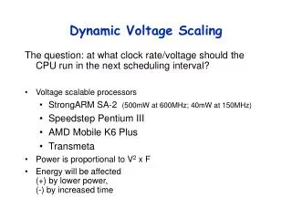
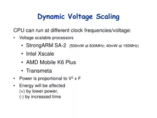
DVFS Background Pdyn = αCVdd2f E = CVdd2 td ≈ CVdd/(Vdd−Vt)α Vdd↓ f↓ => Pdyn,leak ↓ Vdd↓ => E ↓ Vdd↓ => td ↑ fmax ↓ • Reducing supply voltage: • Reduces power and energy dissipation • Reduces maximum clock frequency due to increased gate delay
Other DVFS Schemes Scheme1: Off-chip DC-DC Converter Scheme 2: On-chip DC-DC Converter
Presented DVFS Scheme • Fine grain voltage scaling • Maximum power/energy reduction with minimum performance overhead • Small area overhead by using an off-chip DC-DC converter, and switching between voltages on-chip
Outline • Background and Motivation • Implementation • Results
Implementation Schematic • Voltage scaling with 2 discrete voltage levels • Supply switching with PMOS power gates • Automated DVFS based on workload • Wrapper powered by always on power supply
Power Gate Sizing W/L ↑ VPG ↓ td ↓ fmax ↑ VPG = IPGRPG RPG ~ L/W td ≈ CVdd/(Vdd −VPG −Vt)α Voltage drop can be reduced by making W/L as large as possible → done by adding parallel power gates
Supply Switching Scheme • Supply grid noise: • Gradually switch between power supplies • Shorting between power supplies: • Shut both power supplies off and wait for some time before switching • Data corruption: • Stall the processor core before switching between power supplies
Dynamic Run-time Supply Switching Circuit • Wait for request • Stall core • Shut off power • Delay • Supply switch • Release stall
Physical Implementation • Power gates are positioned along vertical power stripes • Core power is supplied with horizontal power stripes
Outline • Background and Motivation • Implementation • Results
Implementation Results • Implemented in 65nm CMOS technology • DVFS circuit area is 12% of AsAP processor’s core area • 66% of the DVFS circuit area is power gates and decoupling capacitors • Maximum power consumption of DVFS logic is 4% of AsAP processor core’s power
Energy Consumption Metric • Pdyn = αCVdd2f • E = CVdd2 • Energy reduction is possible only with voltage scaling • EDP = E * td • Energy delay product measures the effect of increased delay with DVFS
Measurement of Relative Energy Delay Product • β is the fraction of time operating on the lower voltage • tdvfsis the total run time with DVFS • torigis the total run time without DVFS.
9 Processor JPEG Application Vddhigh = 1.3V, Vddlow = 0.8V Maximum Frequency = 1.05 GHz • Lower minimum frequency →Increase in time on lower supply • EDP decreases as the minimum frequency decreases up until 13 MHz • EDP increases as the performance overhead outweighs the energy savings
Various Applications Vddhigh = 1.3V, Vddlow = 0.8V Maximum Frequency = 1.05 GHz • EDP dependent on workload variations • Increase in workload variation → Increase in switching between supplies → Increase in performance overhead → Increase in EDP
Summary • DVFS with 2 supply voltages • Power gates sized to reduce perf. loss • Robust supply switching circuit • EDP is reduced by 48% on a 9 processor JPEG application • Functional in silicon at 65nm node
Acknowledgements • Funding • Intel Corporation • UC Micro • NSF Grant No. 0430090 • CAREER award 0546907 • SRC GRC Grant 1598, • IntellaSys Corporation • S Machines • Uniquify Inc. • Special thanks • Members of the VCL, R. Krishnamurthy M. Anders, and S. Mathew • ST Microelectronics and Artisan