Download
1 / 11
110 likes | 215 Views
Dynamic Voltage Scaling Using Both Headers and Footers. Kyle Craig and Roy Matthews ECE 632. Background. Our research has addressed the power savings method known as Dynamic Voltage Scaling (DVS) to a system and attempt to apply the use of both headers and footers in the process.

E N D
Dynamic Voltage Scaling Using Both Headers and Footers Kyle Craig and Roy Matthews ECE 632
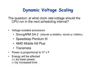
Background • Our research has addressed the power savings method known as Dynamic Voltage Scaling (DVS) to a system and attempt to apply the use of both headers and footers in the process. • Low power design is a crucial area of VLSI research and quadratic power savings can be achieved by voltage reduction, using the following formula: Pdyn=aCVDD2f. • DVS allows us to take advantage of this power savings. • We have performed simulations using a DVS system of headers and footers on a 32-bit Kogge-Stone Adder using the 65nm TT PTM
Voltage Scaling Power Power Delay Delay The relationship between power and delay is shown above. Tradeoffs must be considered when implementing a DVS system.
Header and Footer Sizing for Delay • Adding power gates to a system will cause an increase in delay. • Headers and footers must be sized appropriately to achieve an established metric. • We can see using VDDH that a 50% decrease in header width, a 1.1% delay increase and 40% power reduction. • Similarly, using VSSL a 50% decrease in footer width yields a 1.5% increase in delay and 13% reduction in power. Delay Delay Power Power Delay Power
Header and Footer Sizing for Delay • Comparing header sizing for VDDH against VDDL shows that larger headers are required to achieve a similar delay metric. • As before, if we use VDDL and reduce width by 50%, the delay increases by 2.1% and the power decreases by 42%. Delay Power Delay Power
Virtual Rail Recovery • The normalized delay can be seen here against total power for the system. • Any time and width combination meeting our delay constraint of 10% is highlighted. • A global case without headers showed a power of 2.71mW, so every case here saves some energy. • Average total power is calculated here as the sum of the rail recovery power and the power for the operation.
Virtual Rail Recovery • Footer rail recovery can be seen here as compared to header rail recovery. • Footers require a much smaller area to achieve the same delay penalty, which can be leveraged when designing DVS circuits, though power savings is less than for the header cases.
Switching Energy Overhead • Switching energy overhead is very large in this case of an idle Kogge-Stone adder. • This must be taken into account when switching from VDDL to VDDH.
Sizing as a Knob Footer Footer • Comparing the power consumption of a system only using headers versus only using footers shows some interesting results. • These different slopes can be leveraged as separate knobs to achieve greater control over power and width. Header Header Footer Header
Future Research • Circuit Body Bias • Sensitivity Study of DVS with Headers and Footers • Tradeoffs for using both headers and footers for leakage control (similar to MTCMOS).
Conclusions • Any DVS system trades area for power savings and designing for headers and footers created additional complexity. • However, such a system would allow for more knobs, to give designers more options when weighing power, delay, and area considerations.