Download
1 / 23
230 likes | 364 Views
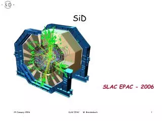
SiD EMCal Testbeam Prototype. M. Breidenbach for the SiD EMCal and Electronics Subsystems. ECAL. t 142 mm. D 2.5 m. L 4.36 m. Prototype Goals: Replicate full EMCal stack and test – 30 sensors. 20 layers 2.5 mm W (5/7 X0) 10 layers 5 mm W (10/7 X0)

E N D
SiDEMCalTestbeam Prototype M. Breidenbach for the SiDEMCal and Electronics Subsystems
ECAL t 142 mm D 2.5 m L 4.36 m • Prototype Goals: • Replicate full EMCal stack and test – 30 sensors. 20 layers 2.5 mm W (5/7 X0) 10 layers 5 mm W (10/7 X0) 30 gaps 1.25 mm w Si pixels sensors 29 X0; 1 λ ΔE/E = 17%/E; Effective Moliere radius = 13 mm SiD Meeting August 2012
Boundary Conditions • We have 40 nominally good Hamamatsu sensors. • We have ~20 nominally bad “mechanical prototype” sensors. • We have 28 remaining KPiXa (1024 channels). • The KPiXa’s come from TSMC with eutectic Sn-Pb bumps in place in wells on the chip. • The Hamamatsu sensors (EMCal and Tracker) come with Al pads, so there is a layer of Al2O3 which must be removed… SiD Meeting August 2012
Under Bump Metallization (UBM) • UCD put a huge effort into UBM: • Used the mechanical prototype sensors • Zincate – chemistry to remove the Al2O3 and plate a stack ending with Au. • Sputtering – to directly implant Ti and then a stack ending with Au. • With miserable results! • Possible explanation is that there is something else on the pads, but SEM sees only Al and O. • We finally went to IZM in Germany who use a sputtering process. • They have bonded two KPiXa’s to two mechanical prototype sensors. X-ray image of bumps - IZM SiD Meeting August 2012
Bonded Sensor • UCD has bonded a cable to one; it is being tested at SLAC. • UO is probe testing the other. First results ~now. KPiX bump bonded to sensor Cable bump bonded to sensor Assembly 1 mm high SiD Meeting August 2012
Results… • 752 pixels seem ok. • 114 pixels appear disconnected – no apparent increase in noise as expected from increased C. • 158 pixels do not calibrate properly – leakage? • But this is a mechanical prototype!!! • UO has probed a few other prototype sensors, and sees ~3% opens. • We do not yet have the corresponding good/open/bad pixel numbers for the UO sensor. SiD Meeting August 2012
First Performance Studies Cross talk Study: Red: 4 pixels pulsed at 500 fC, All other channels shown. Blue: no pixels pulsed. Cosmic telescope trigger SiD Meeting August 2012
Performance Comments • The first version of the electronics reading out KPiX gave excellent “analog” performance – e.g. self triggered multiplicity was ~1, and there were no “everything lights up” events. • This indicates that KPiX and its sensor, cable, and enclosure environment is satisfactory. • The new electronics, suitable for 32 KPiX, is not quiet. • It is probably ok for the testbeam (short window), but the system needs work.
Prototype • Silicon sensors: Meet specs. for SiDEcal • low leakage current; DC coupled • sufficient number for prototype (30 layers) • KPiX: prototypes meet SiD specs.: • low noise (10% of MIP) • large dynamic range: ~104 • full digitization and multiplexed output • passive cooling (power pulsing) • Interconnects: • Flex cable R&D ok so far – successful attachment to dummy sensors and 1 mechanical prototype. • Main focus of recent R&D is the KPIX – sensor interconnects … recently successful – we think… Prototype module – circa LOI SiD Meeting August 2012
Prototype – Engineering Model SiD Meeting August 2012
Layer Assembly SiD Meeting August 2012
Adding hold-down tabs SiD Meeting August 2012
Layer SiD Meeting August 2012
Assembly Tooling SiD Meeting August 2012
Study showing concentrator board SiD Meeting August 2012
With Cover SiD Meeting August 2012
Cable Transition Board • Signals • Power • AVVD (2 pins) • AGND (2 pins) • DVDD (2 pins • DGND (2 pins) • Bias • Bias Pos (1 pins) • Bias Neg (1 pins) • Signal • Clock (2 pins) • Trigger (2 pins) • Reset (1 pin) • Command (1 pin) • Data (1 pin) • Return (1 pin) PowerFilter Cable Clk Term Edge Connector TrigTerm Bias Filter • Clock & trigger LVDS termination • Power supply filtering • Bias filtering • Edge connector • Right angle 0.1” pins • 18 pins SiD Meeting August 2012
Cable Concentrator Board Control & Data Fiber Clock Dist. Bias Conn Trigger Dist. FPGA Clock & Trig Fiber Edge Connectors (30) Reset Dist. Optional Trig. Conn. Optional Regulators Power Conn Cmd / Data Buffers Pwr Conn • Bias input and distribution • KPIX power input and distribution • Direct AVDD/DVDD feed or local linear regulator • Clock, trigger & reset distribution • Per sensor command & data connection • Concentrator FPGA • Optical control and data interface • 3.125gbps PGP • Optical timing / trigger interface • Embedded EVR firmware • Optional TTL trigger input • Separate FPGA power connector SiD Meeting August 2012
Production • All W plates are in hand. • Conceptual design drawings for mechanics complete; final drawings shortly. • 40 good sensors have been sent to IZM. • 28 KPiXa’s (all we have) are on their way to IZM. • IZM will produce 1 batch of 15 for evaluation. • We hope to do a production run on more KPiX 1024 channel chips. • Probe testing available at UO. • UCD will manufacture and attach cables. • Testing of cabled sensors at SLAC. • Assembly and testing of system (pre-testbeam) at SLAC. SiD Meeting August 2012
Software • A new back end system that will handle 32 KPiX is being built, and data and calibration formats have been set. • Data will be accessible with JAS3, and single KPiX testing is underway. • UO has built a single event display. SiD Meeting August 2012
ESTB Mission and Layout • ESTB will be a unique HEP resource • World’s only high-energy primary electron beam for large scale Linear Collider MDI and beam instrumentation studies • Exceptionally clean and well-defined primary and secondary electron beams for detector development • Will serve a broad User community Test EMCal Pulsed magnets in beam switch yard to send LCLS beam to ESA SiD Meeting August 2012
Test Expectations • Expect to take data with a precisely synchronous bunch – what KPiX was designed for. • Expect to take data at a range of energies and with mean e+ multiplicity ~1. • Measure energy and spatial resolution. • Characterize KPiX in “synchronous” mode: noise, cross talk, channel uniformity, etc. • Most important – look for problems with the basic approach. SiD Meeting August 2012