Download
1 / 29
290 likes | 299 Views
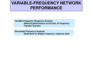
VARIABLE-FREQUENCY NETWORK PERFORMANCE. LEARNING GOALS. Variable-Frequency Response Analysis Network performance as function of frequency. Transfer function. Sinusoidal Frequency Analysis Bode plots to display frequency response data. Resonant Circuits

E N D
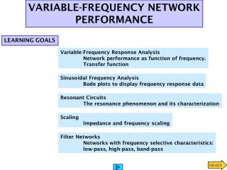
VARIABLE-FREQUENCY NETWORK PERFORMANCE LEARNING GOALS Variable-Frequency Response Analysis Network performance as function of frequency. Transfer function Sinusoidal Frequency Analysis Bode plots to display frequency response data Resonant Circuits The resonance phenomenon and its characterization Scaling Impedance and frequency scaling Filter Networks Networks with frequency selective characteristics: low-pass, high-pass, band-pass
RESONANT CIRCUITS These are circuits with very special frequency characteristics… And resonance is a very important physical phenomenon The frequency at which the circuit becomes purely resistive is called the resonance frequency
Properties of resonant circuits At resonance the impedance/admittance is minimal Current through the serial circuit/ voltage across the parallel circuit can become very large (if resistance is small) Given the similarities between series and parallel resonant circuits, we will focus on serial circuits
Phasor diagram for series circuit Phasor diagram for parallel circuit Properties of resonant circuits At resonance the power factor is unity
Determine the resonant frequency, the voltage across each element at resonance and the value of the quality factor LEARNING EXAMPLE
Given L = 0.02H with a Q factor of 200, determine the capacitor necessary to form a circuit resonant at 1000Hz LEARNING EXAMPLE What is the rating for the capacitor if the circuit is tested with a 10V supply? The reactive power on the capacitor exceeds 12kVA
LEARNING EXTENSION Find the value of C that will place the circuit in resonance at 1800rad/sec Find the Q for the network and the magnitude of the voltage across the capacitor
dissipates Stores as E field Stores as M field Capacitor and inductor exchange stored energy. When one is at maximum the other is at zero The Q factor Q can also be interpreted from an energy point of view
Evaluated with EXCEL LEARNING EXAMPLE Determine the resonant frequency, quality factor and bandwidth when R=2 and when R=0.2
A series RLC circuit as the following properties: LEARNING EXTENSION Determine the values of L,C. 1. Given resonant frequency and bandwidth determine Q. 2. Given R, resonant frequency and Q determine L, C.
dependent For example LEARNING EXAMPLE Find R, L, C so that the circuit operates as a band-pass filter with center frequency of 1000rad/s and bandwidth of 100rad/s Strategy: 1. Determine Q 2. Use value of resonant frequency and Q to set up two equations in the three unknowns 3. Assign a value to one of the unknowns
PROPERTIES OF RESONANT CIRCUITS: VOLTAGE ACROSS CAPACITOR But this is NOT the maximum value for the voltage across the capacitor
Evaluated with EXCEL and rounded to zero decimals LEARNING EXAMPLE Natural frequency depends only on L, C. Resonant frequency depends on Q. Using MATLAB one can display the frequency response
R=50 Low Q Poor selectivity R=1 High Q Good selectivity
The Tacoma Narrows Bridge LEARNING EXAMPLE Opened: July 1, 1940 Collapsed: Nov 7, 1940 Likely cause: wind varying at frequency similar to bridge natural frequency
0.44’ 1.07’ Tacoma Narrows Bridge Simulator Assume a low Q=2.39
Series RLC Parallel RLC Series RLC Parallel RLC PARALLEL RLC RESONANT CIRCUITS Impedance of series RLC Admittance of parallel RLC
If the source operates at the resonant frequency of the network, compute all the branch currents LEARNING EXAMPLE
Derive expressions for the resonant frequency, half power frequencies, bandwidth and quality factor for the transfer characteristic Replace and show LEARNING EXAMPLE
LEARNING EXAMPLE Increasing selectivity by cascading low Q circuits Single stage tuned amplifier
Parallel RLC Determine the resonant frequency, Q factor and bandwidth LEARNING EXTENSION
Parallel RLC Can be used to verify computations LEARNING EXTENSION
The resistance of the inductor coils cannot be neglected PRACTICAL RESONANT CIRCUIT How do you define a quality factor for this circuit?
Resonance RESONANCE IN A MORE GENERAL VIEW For series connection the impedance reaches maximum at resonance. For parallel connection the impedance reaches maximum A high Q circuit is highly under damped
Constant Q networks SCALING Scaling techniques are used to change an idealized network into a more realistic one or to adjust the values of the components Magnitude scaling does not change the frequency characteristics nor the quality of the network.
LEARNING EXAMPLE Determine the value of the elements and the characterisitcs of the network if the circuit is magnitude scaled by 100 and frequency scaled by 1,000,000
Scaling LEARNING EXTENSION