Download
1 / 13
130 likes | 226 Views
Particle acceleration by circularly polarized lasers. W-M Wang 1,2 , Z-M Sheng 1,3 , S Kawata 2 , Y-T Li 1 , L-M Chen 1 , J Zhang 1,3. 1 Institute of Physics, Chinese Academy of Sciences, Beijing, China 2 Utsunomiya University, Utsunomiya, Japan

E N D
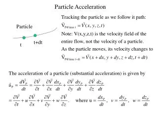
Particle acceleration by circularly polarized lasers W-M Wang1,2, Z-M Sheng 1,3, S Kawata2, Y-T Li1, L-M Chen1, J Zhang1,3 1Institute of Physics, Chinese Academy of Sciences, Beijing, China 2Utsunomiya University, Utsunomiya, Japan 3Shanghai Jiao Tong University, Shanghai, China
Why do we employ CP lasers ■ Ponderomotive force of a circularly polarized (CP) laser pulse has a much larger acceleration phase than a linearly polarized (LP) laser pulse.
Ion acceleration by CP lasers ■ 2007-2008, several groups proposed to use a CP laser to accelerate ions of a thin solid foil, which called as RPA or PSA. The CP laser pushes electrons directly and the electrons pull ions. X Zhang et al, Phys. Plasmas 14, 123108 (2007); X Q Yan et al, Phys. Rev. Lett. 100 ,135003 (2008); A Robinson et al, New J. Phys. 10, 013021 (2008); O Klimo et al, Phys. Rev. ST Accel. Beams 11, 031301 (2008)
Acceleration with an ion-mixed foil ■ A foil is composed with a variety of ions, usually.
Three regimes in RPA PIC simulations ■Regime I: I0 is low. Protons and ions are accelerated together. ( I0<Ii) ■Regime II: I0 is moderate. Only protons are accelerated. ( Ip<I0<Ii) ■Regime III: I0 is large. Neither is accelerated. ( I0>Ip) W-M Wang et al., Plasma Sci. Technol. 12, 277 (2010)
Efficient proton acceleration in Regime II ■ Proton acceleration of the ion-mixed foil (20% protons)is more efficient than the pure proton foil (100% protons).
Electron acceleration in Regime III ■ We can use a CP laser to accelerate foil electrons. Why shall we do in this way?Two reasons. Ability: the laser technology has been developing to be more intense and resulting shorter (e.g. ELI lasers), which can drive the ponderomotive field/force acceleration (LPFA) very efficiently. Necessity: further laser pulses (a few fs, much shorter than λp)are not optimized for laser wakefield acceleration (LWFA). Its acceleration efficiency can be exceeded by LPFA. (0.34a0 MeV in LWFA vs 0.26 a02 MeV in LPFA) ■To get high energy electron beams, LPFA is an alternative with the ultrashort ultraintense lasers.
A feasible scheme of LPFA for monoenergetic beams W-M Wang et al., Phys. Rev. ST Accel. Beams 13, 071301 (2010) ■ Thin source foil. 1) Easy electron trapping by ponderomotive field. 2) Monoenergetic and short electron burst. ■ Prediction can be given by the single electron model. GeV electron beams can produce by 13fs, 1022W/cm2 laser with the acceleration distance 1.8 mm. TeV electron beams can produce by 13fs, 1025W/cm2 laser with the acceleration distance 1.8 m.
Demonstration by 1D PIC simulations I0=1022W/cm2; Sine temporal waveform with the duration 13.3 fs; Wavelength 1 um. Foil density 100 nc ; Thickness 1nm. Without blocking thick foil ■ Energy up to 800MeV,acceleration time is a few ps or about 1 mm (930 MeV, 6.1 ps and 1.8 mm in the model). ■ At 3.15 ps, energy spread 0.24%, and the burst duration 0.4 um.
Change the thickness of the source thin foil ■ Energy from 1-10nm foils approaches the prediction. For the 100nm foil, the energy is higher than the prediction. ■ With the increase of the thickness, the spread grows, and the trapped electrons are decreased.
2D PIC simulation results I0=1022W/cm2; Sine temporal waveform with the duration 6.7 fs; Spot radius 10 um (Gaussian); Wavelength 1 um. 20nm, 5 nc source foil (=1nm, 100 nc foil) 100nm, 200nc reflecting thick foil at 618.5 um, ■ Energy about 600MeV, the energy spread 0.7%, and the burst duration 0.4um. ■ Stable acceleration for 2ps due to the relativistic mass increase rapidly. ■ Transverse motion. It will be very slight, when the intensity is large.
■ LPFA can produce highenergy ultrashort monoenergetic electron beams efficiently. ■ GeV-TeV electron beams are produced by the 1022-1025 W/cm2 lasers. ■ Electron acceleration distance in the ultraintense laser regime is large enough to allow one to separate the beam from the laser before the beam is decelerated. ■ Electrons are accelerated to gain large relativistic masses quickly, which keeps the acceleration stable for a long time. ■ For the ultrashort ultraintense lasers, LPFA has the larger acceleration field and can produce higher energy electron beams than LWFA. Conclusions