Download
1 / 24
270 likes | 361 Views
Jan Östlund KTH, Royal Institute of Technology, Stockholm, Sweden VAC, Volvo Aero Corporation, Trollhättan, Sweden. Supersonic Flow Separation with Application to Rocket Engine Nozzles. Motivation Background/Perspective Methods Origin of Side-Loads Conclusions.

E N D
Jan Östlund KTH, Royal Institute of Technology, Stockholm, Sweden VAC, Volvo Aero Corporation, Trollhättan, Sweden Supersonic Flow Separation with Application to Rocket Engine Nozzles
Motivation Background/Perspective Methods Origin of Side-Loads Conclusions Outline of the Presentation
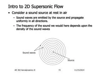
Core stage engines continuously operate from sea-level (1 bar) to high altitudes (near vacuum) (e.g. Vulcain, LE-7A, SSME) pe<pa pe=pa pe>pa Motivation Flow separation essential factor limiting • the performance of core stage rocket engines • the payload capacity of the launch vehicle Increasing performance pe << psea-level Nozzle flow will separate at sea-level Large fluctuating lateral forces, “side-loads” Trade off between reliable engine operation at sea-level and high vacuum performance Decreasing ambient pressure
Motivation Design for optimal performance requires models for accurate prediction of • separation point location • side-load levels • Both at design and off-design conditions (start up and shut down transients) First Vulcain TC test 1989 Inaccurate predictions can have dramaticconsequences
Background/Perspective • Several basic questions unanswered: • What is the source of side-loads? • Aeroelasticity, random pressure fluctuations, a combination or something else? Side-loads due to aeroelastic instability “Model results are qualitatively as well as quantitatively consistent with Vulcain test results” • Side-loads due to random pressure fluctuations • Good agreement between measured and predicted side-load for Russian rocket nozzles • However, model can not reproduced the Vulcain side-loads Tilted separation line Aeroelastic instability Pressure pulsations New research initiated 1974 Schmucker 1989 First Vulcain TC test 1994 Pekkari 1996 Dumnov 1997 Östlund
Methods Contour layout MOC/CFD Internal flow field Separation pattern CFD Physical phenomena: Test Analytical / numerical models for prediction of phenomena in a real nozzle Correlation: analysis Current work: • Investigation of nozzle flow separation and side-loads using a combination of analytical, numerical and experimental methods
Scale tests Full-scale, hot gasFinal hardware development tests Sub-scale, hot gas “Demonstrator” test Representativity of obtained results Sub-scale, cold gas Scientific or “basic” research Sub-scale full-scale : Step needed here from cold gas to hot reacting gas! Complexity of test setup
Scale-tests • The Volvo sub scale tests have been the basis for the understanding of separation and side-load characteristics in Vulcain and similar nozzles • Due to correct scaling, these sub-scale models successfully rendered the characteristic behavior of a real rocket engine nozzle
The problem of side-loads substantially more complex than previous realized Side-loads generated by a varity of physical mechanisms Depends on nozzle contour type, mechanical structure and ambient conditions Three main mechanisms for side-loads have been identified Origin of side-loads
Origins of Side-Loads – 1: Pressure Fluctuations Flow Separation in Rocket Nozzles - SWTBLIUnsteady and 3-dimensional phenomenon The photo shows the SSME during start-up. The film clip shows the SSME during start-up.
Origins of Side-Loads - Pressure Fluctuations M=5 Flow separation in rocket nozzlesrelated toSWTBLI in Basic Interactions Separation shock motionintermittent pressure fluctuations Experiment by Yongxi Hou, Roderick G. Austin, Steven J. Beresh, Mark Comninos, Stephen C. Chan, David S. Dolling and Noel T. Clemens http://www.ae.utexas.edu/research/FloImLab/shock.html
Origins of Side-Loads – 1: Pressure Fluctuations • Side-loads can be resolved into two components: • a low frequency buffeting caused by changes in the geometry of the separation region • high frequency fluctuations originating from the shear layer of the separated region • Side-loads prediction requires knowledge of: • separation position • interaction length • rms level of pressure fluctuations • Power Spectral Density (PSD) of the pressure pulsations • Spatial-frequency Cross Spectral Density (CSD) of the pressure pulsations Flow separation model • Dumnov (1996) stated that the PSD and CSD are universal functions that can be applied to different nozzles using appropriate scaling laws. However, no such functions or scaling laws were presented.
Origins of Side-Loads – 1: Pressure Fluctuations + + Model: flow separation time averaged quantities Model: rms pressure Model: Pressure PSD + Model: CSD of the pressure fluctuations Prediction of Side-load
Fluctuating pressure load excitate different nozzle modes Fluid/Structure interaction possible, i.e. aeroelasticity Origins of Side-Loads – 2: Aeroelastic Coupling a) Pendulum- b) Bending- c) Ovalisation- and d) Triangular-mode Rocket Engine Nozzle Structural eigenmodes
Origins of Side-Loads – 2: Aeroelastic Coupling Aeroelastic coupling of the bending mode can produce side-loads Undeflected nozzle Deflected nozzle Induced aeroelastic torque Ma
Origins of Side-Loads – 2: Aeroelastic Coupling • Aeroelastic model by Pekkari (VAC), 1994 • The model was modified and improved by Östlund • Unique test set-up designed by Östlund for: • investigation of aeroelastic effects in rocket nozzles • validation of model • Experimental verification: • Aeroelastic effects exists in separated nozzles • However, side-loads in Vulcain, not due to aeroelastic coupling • The improved aeroelastic model able to predict the phenomena Fixed part Flexible hinged part Bending mode of a real nozzle emulated by a flexible hinged model nozzle analytical description of mechanical system possible Torsion spring
Origins of Side-Loads – 3: Transition of Separation Pattern pa pp pa pp pi pi Mach disc, regular reflection, or cap-shock Cap-shock Free Shock Separation (FSS) Restricted Shock Separation (RSS) Mach disc, regular reflection, or cap-shock Cap-shock
Restricted Shock Separation • Restricted shock separation was first observed during cold-flow sub-scale tests for the J-2 engine development in the early 70s, but: • the reason for the re-attached flow remained unclear, and • it was believed that RSS only occurs in cold-gas sub-scale nozzles • The re-attached flow in the J-2S sub-scale nozzles was first confirmed by numerical simulations in 1994, but again without giving a physical explanation • Östlund et al. observed RSS pattern in cold sub-scale test of Vulcain 1997 and showed that it is crucial importance for side-load generation. This caused renewed interest in the phenomenon and ignited world wide intensive research. • Subsequent re-evaluation of earlier full-scale engine tests also revealed RSS in the Vulcain, the SSME and the LE-7A nozzle
Different contour types produce their own specific internal flow field 15o cone TIC TOC TOP Origins of Side-Loads – 3: Transition of Separation Pattern RSS specific feature in nozzle contours with internal shock Common rocket nozzle types: Conical TICTruncated Ideal Contour TOCThrust Optimised Contour TOPThrust Optimised Parabola Mach number distribution in different contours. The thick line indicates the approximate position of the internal shock.
Origins of Side-Loads – 3: Transition of Separation Pattern FSS RSS transition only in nozzles with internal shock cap-shock pattern Cap-shock pattern provides flow with lateral momentum towards wall RSS
Origins of Side-Loads – 3: Transition of Separation Pattern • Side-loads due to non-symmetrical change from FSS to RSS Volvo S1
Tilted separation line Aeroelastic instability Pressure pulsations 1974 Schmucker 1989 First Vulcain TC test 1994 Pekkari 1996 Dumnov Conclusions • Side-loads are generated by a variety of of physical mechanisms, i.e. not only one • Pressure pulsations • Aeroelastic effects • Transition of separation pattern in nozzle, The key driver for the side-loads in the Vulcain nozzle. • Östlund was the first to discover the role of FSS RSS transition for side-load generation by: • experimental verification • CFD analysis • Östlund has also contributed to the experimental verification and analysis of aeroelastic effects Transition of separation pattern 1997-2004 Östlund et. al.
Successful combination of establishment of scaling laws, analysis of experimental data, numerical simulations, and analytical approaches have led to significant improvements in the understanding of flow separation and side-load phenomena in rocket engine nozzles Conclusions
Paper 1-2 Description of sub-scale test program and test results Paper 3 Numerical study of flow separation in rocket nozzle Paper 4 Overview of different side-loads mechanisms observed in the test campaigns Description of models aimed for prediction of side-load levels Verification of aeroelastic model Paper 5 Review of the current status of analytical, experimental and numerical research in the field Summary of Papers