Download
1 / 35
370 likes | 585 Views
LVAD System Review. System Overview. Smiha Sayal. System Overview. Left Ventricular Assist Device (LVAD) Mechanical device that helps pump blood from the heart to the rest of the body. Implanted in patients with heart diseases or poor heart function. System Goal.

E N D
System Overview SmihaSayal
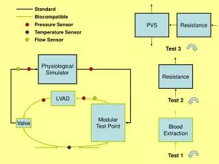
System Overview • Left Ventricular Assist Device (LVAD) • Mechanical device that helps pump blood from the heart to the rest of the body. • Implanted in patients with heart diseases or poor heart function.
System Goal • Miniaturize the existing LVAD system to achieve portability while retaining its safety and reliability.
Engineering Process All team members
Customer Needs • Safe • Robust • Affordable • Easy to wear and use • Interactive with user • Controllable by skilled technician • Comparable performance • Compatible with existing pump
Other LVAD Technologies CorAide (NASA)
Original System • “Black box” architecture used during development • Large, not portable • Runs on AC power
P10021’s System • Has both internal / external components • Equivalent to our “Option 2” • Unfinished implementation
Concepts: Option 1 All electronics external
Concepts: Option 2 ADC internal only
Concepts: Option 3 Pump and motor control internal
Concepts: Option 4 All electronics and battery internal
Concept Generation Highlights Best Option 350 273 200 153
Enclosure Design Nicole Varble and Jason Walzer
Material and Processing Selection • Needs • The external package should be lightweight/ robust/ water resistant • The devices should be competitive with current devices • The device should fit into a small pouch and be comfortable for user • Specification • Optimum weight of 5 lbs • Optimum dimensions of ~6” x 2” x 2” • Risks • Housing for the electronics is too heavy/large/uncomfortable • Preventative measures • Eliminate heavy weight materials • Eliminate weak, flexible materials • Material is ideally machinable
Rapid Prototyping • Dimension System • ABSplus • Industrial thermoplastic • Typically used for product development • Machinable • Material can be dilled (carefully) and tapped • Accepts CAD drawings • Obscure geometries can be created easily • Ideal for proposed ergonomic shape • Lightweight • Specific gravity of 1.04 • Porous • Does not address water resistant need • 0.007” material/layer • Capable of building thin geometries • Builds with support layer • Models can be built with working/moving hinges without having to worry about pins http://www.dimensionprinting.com/
ABS Plastic • Important Notes • Relatively high tensile strength • Glass Transition well above body temperature • Specific Gravity indicates lightweight material
Water Resistant Testing • Need: The external package should resist minor splashing • Specification: Water Ingress Tests • Once model is constructed, (user interface, connectors sealed, lid in place) exclude internal electronics and perform test • Monitor flow rate (length of time and volume) of water • Asses the quality to which water is prevented from entering case • Risk: Water can enter the external package and harm the electronics • Preventative measures: • Spray on Rubber Coating or adhesive • O-rings around each screw well and around the lid • Loctite at connectors http://scoutparts.com/products/?view=product&product_id=14074
Robustness Testing • Need: The device should survive a fall from the hip • Specification: Drop Test • Drop external housing 3-5 times from hip height, device should remain fully intact • Specify and build internal electrical components • Identify the “most venerable” electrical component(s) which may be susceptible to breaking upon a drop • Mimic those components using comparable (but inexpensive and replaceable) electrical components • Goal • Show the housing will not fail • Show electronics package will not fail, when subjected to multiple drop tests • Risks • The housing fails before the electronic components in drop tests • The electronic components can not survive multiple drop tests • Preventative Measures • Eliminate snap hinges from housing (screw wells to secure lid) • Test the housing first • Take careful consideration when developing a thickness of the geometry • Design a “tight” electronics package
Heat Dissipation to the Body • Need: Internal Enclosure dissipates a safe amount of heat to the body • Risk: Internal electronics emit unsafe amounts of heat to body • Benchmarking: • Series of tests studied constant power density heat sources related to artificial hearts • 60-mW sources altered surface temperatures 4.5, 3.4, 1.8 °C above normal at 2, 4, 7 weeks • 40mW/cm2 source increased to upper limit of 1.8 °C • Specifications: Internal devices must not increase surrounding tissue by more than 2°C Wolf, Patrick D. "Thermal Considerations for the Design of an Implanted Cortical Brain–Machine Interface (BMI)." Ncib.gov. National Center for Biotechnology Information, 2008. Web. 30 Sept. 2010. <http://www.ncbi.nlm.nih.gov/bookshelf/br.fcgi?book=frimp∂=ch3>.
Ergonomics • Need: Device should be comfortable for user • ANSUR Database • Exhaustive military database outlining body dimensions • Waist Circumference (114) • Males: 137.3 mm • Females: 126.0 mm • Waist Depth (115) • Males: 113.1 mm • Females: 102 mm • Calculated average radius of hip • Males: 125.2 mm • Females: 114.0 mm • Acceptable Avg. Radius of hip • ~120 mm
Enclosure Concept • CAD model is can be easily resized • Removable top panel for electronics access
Embedded Control System Andrew Hoag and Zack Shivers
Control System • Requirements • Selecting suitable embedded control system • Designing port of control logic to embedded system architecture • Customer Needs • Device is compatible with current LVAD • Device is portable/small • Allows debug access
Impeller Levitation • Impeller must be levitating or “floating” • Electromagnets control force exerted on impeller • Keeps impeller stabilized in the center • Position error measured by Hall Effect sensors
Levitation Algorithm • Algorithm complexity influences microcontroller choice • Electronics choices affect volume / weight • Proportional – Integral – Derivative (PID) • Very common, low complexity control scheme http://en.wikipedia.org/wiki/PID_controller
Embedded System Selection • Requirements: • Can handle PID calculations • Has at least 8x 12-bit ADC for sensors at 2000 samples/sec • Multiple PWM outputs to motor controller(s) • Same control logic as current LVAD system • Reprogrammable
Embedded System Selection • Custom Embedded • dsPIC Microcontroller • Blocks for Simulink • Small • Inexpensive (<$10 a piece) • TI MSP430 • Inexpensive (<$8 a piece) • Small, low power • COTS Embedded • National Instruments Embedded • Uses LabVIEW • Manufacturer of current test and data acquisition system in “Big Black Box” • Large to very large • Very expensive (>$2000)
Control Logic/Software • Closed-loop feedback control using PID – currently modeled in Simulink for use with the in “Big Black Box” • Additional microcontroller-specific software will be required to configure and use A/D, interrupts, timers.
Life Critical System • Not at subsystem level detail yet. • Life-critical operations would run on main microcontroller. • User-interface operations run on separate microcontroller. • Possible LRU (Least Replaceable Unit) scheme
Questions / Comments Help us improve our design!