Download

1 / 15
150 likes | 257 Views
11022 Transcutaneous Signal Transmission for LVAD. February 18 , 2011 Yevgeniy Popovskiy, Vince Antonicelli, Craig LaMendola , Chrystal Andreozzi. Senior Design Review Agenda. Introduction Design Test Results Successes Challenges Recommendations. Project Background.

E N D
11022 Transcutaneous Signal Transmission for LVAD February 18 , 2011 Yevgeniy Popovskiy, Vince Antonicelli, Craig LaMendola , Chrystal Andreozzi
Senior Design Review Agenda Introduction Design Test Results Successes Challenges Recommendations
Project Background The Left Ventricular Assist Device (LVAD) is a electro mechanical circulatory device designed to assist a patient with a failing heart. Typically, a patient will receive one for temporary use after a heart attack or major heart surgery. Eliminate as many transcutaneous wires as possible running from the external battery and controller to the LVAD.
Customer Needs and Engineering Specifications THE SYSTEM NEEDS TO WORK!!!! • Must Operate Reliably for 6 hours • Cable Size Reduced to 3-4mm • Improve Cable Flexibility by 200% The device must be reliable The number of wires needs to be reduced The cable diameter needs to be reduced The cable needs to be more flexible
Big Picture Design External Case “Big Black Box” ICs Internal Case Skin LVAD ICs Motor Controller Amplifiers
Electronics Function The Big Black Box SKIN 3 1 2 SA Sensors MCC + MCT Motor Controller Amplifiers PAAS=>PADS
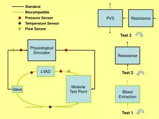
Test Results Electronics Functionality Test Leak and Pressure Test Drop Test Flexibility Testing
Electronics Functionality Test Outside PWBA SA Signals In (Bottom)and Out(Top from Set Up On Bread Board Inside PWBA MCC Data from PWBA
Drop Test • Both cases were drop tested with boards inside • Cases sealed with o rings • Boards mounted with thermally conductive foam • External case had neoprene cover installed • Both cases dropped 3 times from 1 meter height • No damage observed to cases or electronics
Leak and Pressure Test • Both cases were sealed only with o ring cords • Silicone sealant not used for testing • Sections of actual cables installed in cord grips • Cases were sealed, tested, and examined three times • Tested under .75 meters of water for 90 minutes • Tested under running water for 15 minutes • Cases confirmed water tight under pressure
Flexibility Testing • 310% Increase in Flexibility • Cable diameter is 3.7 mm
Challenges Time restraint on Debug Electrical System Timely Coordination of information exchange Major design changes from concept to finial design Communication Coordinating with the other team
Successes Cases easily past testing requirements Cable diameter was reduced and flexibility increased Successfully utilized breadboard as a cost efficient prototyping tool Got breadboard to function properly
Recommendations Combining all electronics used in project 11022 and project 11021 Reduce physical size of internal and external electronics by combining all internal electronic components into one compact design Use the same tool form the simulation and finial electronics layout (example PADS)