Download
1 / 7
90 likes | 97 Views
The heating, ventilation, and air conditioning HVAC system is arguably the most complex system installed in a building and is responsible for a substantial component of the total building energy use. Maintaining optimal temperature and air circulation are the basis of a comfortable indoor environment 1 . This role is played by HVAC Heating, ventilation and air conditioning systems. The heat load calculations along with the duct design for a HVAC system installed in a multistorey residential building is calculated and analyzed to maintain a desired temperature based on outer environmental temperature. The duct design is analyzed which create an impact on system performance. The layout of a multistorey residential building is made by using Autodesk REVIT software. A complete air conditioning system was designed along with ducts and VAV system to control the indoor environment conditions like temperature, relative humidity, air movement, etc. Based on the obtained Heat Load Calculations CFM and T.R values were found for each spaces and ducting design was done for all the spaces by considering the quantity of CFM to be supplied. A suitable air handling unit AHU is selected based on the CFM value for multi storey residential building. With this the capacity of equipment was estimated and selected for the installation. Basavaraja K. T | T. Kiran | T. Sushanth | Thummala Saiteja Reddy "Heat Load Calculation with Duct Design of a Multi Storeyed Residential Building" Published in International Journal of Trend in Scientific Research and Development (ijtsrd), ISSN: 2456-6470, Volume-3 | Issue-3 , April 2019, URL: https://www.ijtsrd.com/papers/ijtsrd23301.pdf Paper URL: https://www.ijtsrd.com/engineering/mechanical-engineering/23301/heat-load-calculation-with-duct-design-of-a-multi-storeyed-residential-building/basavaraja-k-t<br>

E N D
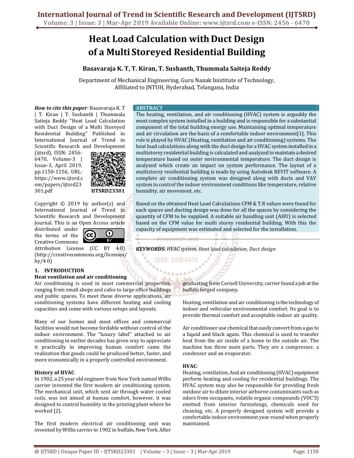
International Journal of Trend in Scientific Research and Development (IJTSRD) Volume: 3 | Issue: 3 | Mar-Apr 2019 Available Online: www.ijtsrd.com e-ISSN: 2456 - 6470 Heat Load Calculation withDuct Design of a MultiStoreyed Residential Building Basavaraja K. T,T. Kiran,T. Sushanth,Thummala Saiteja Reddy Department of Mechanical Engineering, Guru Nanak Inistitute of Technology, Affiliated to JNTUH, Hyderabad, Telangana, India How to cite this paper: Basavaraja K. T | T. Kiran | T. Sushanth | Thummala Saiteja Reddy "Heat Load Calculation with Duct Design of a Multi Storeyed Residential Building" Published in International Journal of Trend in Scientific Research and Development (ijtsrd), ISSN: 2456- 6470, Volume-3 | Issue-3, April 2019, pp.1150-1156, URL: https://www.ijtsrd.c om/papers/ijtsrd23 301.pdf Copyright © 2019 by author(s) and International Journal of Trend in Scientific Research and Development Journal. This is an Open Access article distributed under the terms of the Creative Commons Attribution License (CC BY 4.0) (http://creativecommons.org/licenses/ by/4.0) 1.INTRODUCTION Heat ventilation and air conditioning Air conditioning is used in most commercial properties, ranging from small shops and cafes to large office buildings and public spaces. To meet these diverse applications, air conditioning systems have different heating and cooling capacities and come with various setups and layouts. Many of our homes and most offices and commercial facilities would not become fordable withoutcontrol of the indoor environment. The “luxury label” attached to air conditioning in earlier decades has given way to appreciate it practically in improving human comfort came the realization that goods could be produced better, faster, and more economically in a properly controlled environment. History of HVAC In 1902, a 25 year old engineer from New York named Willis carrier invented the first modern air conditioning system. The mechanical unit, which sent air through water cooled coils, was not aimed at human comfort, however, it was designed to control humidity in the printing plant where he worked [2]. The first modern electrical air conditioning unit was invented by Willis carrier in 1902 in buffalo, New York. After ABSTRACT The heating, ventilation, and air conditioning (HVAC) system is arguably the most complex system installed in a building and is responsible for a substantial component of the total building energy use. Maintaining optimal temperature and air circulation are the basis of a comfortable indoor environment[1]. This role is played by HVAC (Heating, ventilation and air conditioning) systems. The heat load calculations along with the duct design for a HVAC system installed in a multistorey residential building is calculated and analyzed to maintain a desired temperature based on outer environmental temperature. The duct design is analyzed which create an impact on system performance. The layout of a multistorey residential building is made by using Autodesk REVIT software. A complete air conditioning system was designed along with ducts and VAV system to control the indoor environment conditions like temperature, relative humidity, air movement, etc. Based on the obtained Heat Load Calculations CFM & T.R values were found for each spaces and ducting design was done for all the spaces by considering the quantity of CFM to be supplied. A suitable air handling unit (AHU) is selected based on the CFM value for multi storey residential building. With this the capacity of equipment was estimated and selected for the installation. KEYWORDS: HVAC system, Heat load calculation, Duct design IJTSRD23301 graduating from Cornell University, carrier found a job at the buffalo forged company. Heating, ventilation and air conditioning is the technology of indoor and vehicular environmental comfort. Its goal is to provide thermal comfort and acceptable indoor air quality. Air conditioner use chemical that easily convert from a gas to a liquid and black again. This chemical is used to transfer heat from the air inside of a home to the outside air. The machine has three main parts. They are a compressor, a condenser and an evaporator. HVAC: Heating, ventilation, And air conditioning (HVAC) equipment perform heating and cooling for residential buildings. The HVAC system may also be responsible for providing fresh outdoor air to dilute interior airborne contaminants such as odors from occupants, volatile organic compounds (VOC’S) emitted from interior furnishings, chemicals used for cleaning, etc. A properly designed system will provide a comfortable indoor environment year round when properly maintained. @ IJTSRD | Unique Paper ID – IJTSRD23301 | Volume – 3 | Issue – 3 | Mar-Apr 2019 Page: 1150
International Journal of Trend in Scientific Research and Development (IJTSRD) @ www.ijtsrd.com eISSN: 2456-6470 Duct system Duct: Ducts are conduits or passages used in heating, ventilation, and air conditioning (HVAC) to deliver and remove air. The needed air flows include, for example, supplyair, return air, and exhaust air.Ducts commonly also deliver ventilation air as part of the supply air. As such, air ducts are one method of ensuring acceptable indoor air quality as well as thermal comfort. A duct system is also called ductwork. Planning (laying out), sizing, optimizing, detailing, and finding the pressure losses through a duct system is called duct design. Process duct work conveys large volume of hot, dusty air from processing equipment to mills, bughouses to other process equipment. Process duct may be round or rectangular. Although round duct work costs more to fabricate than rectangular ductwork, it requires fewer stiffeners and is favored in many applications over rectangular duct work. The air in process duct work may be at ambient conditions or may operate at up to 900F (482 C) [3]. Process duct work varies size from 2ft diameter to 20 ft diameter or to perhaps 20ft by 40 ft rectangular. Large process duct work may fill with dust, depending on slope, to up to 30% of cross section, which can weigh 2 to 4 tons per linear foot. Round ductwork is subject to duct suction collapse, and requires stiffeners to minimize this. But is more efficient on material than rectangular duct work.1.10 Duct materials Ducts are generally made of the following materials:- ?Galvanized steel ?Aluminum (Al) ?Polyurethane and phenolic insulation panels (pre- insulated air ducts) ?Fiberglass duct board (pre insulated non-metallic ductwork) ?Flexible ducting ?Fabric ducting ?PVC low profile ducting About REVIT Software Autodesk Revit is building information modelling software for architects, landscape architects, structural engineers, MEP engineers, designers and contractors. The original software was developed by Charles River Software, founded in 1997, renamed Revit Technology Corporation in 2000, and acquired by Autodesk in 2002. The software allows users to design a building and structure and its components in 3D, annotate the model with 2D drafting elements, and access building information from the building model's database. Revit is 4D BIM capable with tools to plan and track various stages in the building's lifecycle, from concept to construction and later maintenance and/or demolition. Revit can be used as a very powerful collaboration tool between different disciplines in the building design sphere. The different disciplines that use Revit approach the program from unique perspectives. Each of these perspectives is focused on completing that discipline's task. Companies that adopt the software first examine the existing work flow process to determine if such an elaborate collaboration tool is required. 1.14Modelling through REVIT The Revit work environment allows users to manipulate whole buildings or assemblies or individual 3D shapes. Modeling tools can be used with pre-made solid objects or imported geometric models. However, Revit is not a NURBS modeler and also lacks the ability to manipulate an object's individual polygons except on some specific object types such as roofs, slabs and terrain or in the massing environment. Revit includes categories of objects ('families' in Revit terminology). These fall into three groups: ?System Families, such as walls, floors, roofs and ceilings, built inside a project ?Loadable families/components, which are built with primitives separately from the project and loaded into a project for use ?In-Place Families, which are built in-site within a project with the same toolset as loadable components An experienced user can create realistic and accurate families ranging from furniture to lighting fixtures, as well as import existing models from other programs. Revit families can be created as parametric models with dimensions and properties. This lets users modify a given component by changing predefined parameters such as height, width or number in the case of an array. In this way a family defines a geometry that is controlled by parameters, each combination of parameters can be saved as a type, and each occurrence of a type can also contain further variations. For example, a swing door may be a Family. It may have types that describe different sizes, and the actual building model has instances of those types placed in walls where instance-based parameters could specify the door hardware uniquely for each occurrence of the door. Due to the copyright nature of project work, it is rare and impractical to be able to buy fully 3D modelled Revit project models. Indeed as most projects are site specific and bespoke, obtaining an existing model is in many instances unsuitable. However, there are circumstances where new practices or students that are training to learn Revit, do have a need to refer to completed models. Sources for these are limited, however they can be purchased at websites like BIM Gallery and downloaded from websites like Grab Cad. Although Revit software comes with a range of families out of the box (OOTB), they are limited, so users can find a need to build their own families or buy them from online stores such as Plansort, Bimbandit or Andekan. A number of websites offer families for free including Revit City, AUGI, BIMobject, BIMsmith, National Bim Library and BIM&CO. In 2011 Dynamo was released in beta form allowing first glimpses of directly programming the behavior of hosted components through a drag and drop node interface. This is similar to the way the visual programming language Grasshopper 3d works on objects in Rhinoceros 3D. @ IJTSRD | Unique Paper ID - IJTSRD23301 | Volume – 3 | Issue – 3 | Mar-Apr 2019 Page: 1151
International Journal of Trend in Scientific Research and Development (IJTSRD) @ www.ijtsrd.com eISSN: 2456-6470 2. LITERATURE SURVEY In the paper "Modeling, analysis and state feedback control design of a multi zone HVAC system" the authors have designed a HVAC system for a four floors building and they compared usage data on simulated power and measured data for 3 months and found out that measured data was close to the simulated data[4]. "The necessity of HVAC system for the registered architectural cultural heritage building" highlights the role of the ventilation and air conditioning system for a theatre. Three different scenarios of main hall have been made and studied carefully. "Advanced Energy Design Guide for Small Hospitals and Healthcare Facilities" is a sixth document in the series of guides designed to achieve 30% savings over the minimum code requirements. In the paper "Experimental investigation of noise characteristics for HVAC silencers" the authors felt that it is necessary to control or reduce the noises produced inside the ducting system, so they have tested various types of silencers of different geometry and compare d their efficacies[5]. "Analysis of the impact of simulation model simplifications on the quality of low energy buildings simulation results", deals with, amount of time consumed in simulation of HVAC system for a big building is more so they have worked out a way to do it for a low level building and generalize it for actual building, which is time saving. "Computational intelligence techniques for HVAC systems", this article presents a comprehensive and critical review on the theory and applications of CI techniques for prediction, optimization, control and diagnosis of HVAC systems. In the article "Decentralized optimization for a novel control structure of HVAC system "[6], the authors have discussed about the cost cutting ways in HVAC systems by de- centralizing the control unit and the advantages of it. "Energy demand and thermal comfort of HVAC systems with thermally activated building systems as a function of user profile", presents the numerical Analysis of a HVAC system with TABS energy demand and indoor thermal comfort of a representative room in a nonresidential building. In the paper "A comfort-Aware Energy Efficient HVAC System based on the Subspace Identification Method", deals with the effective way to decrease the energy required for HVAC system by identifying the subspace [7]. "A Hybrid Dynamical Modelling and Control Approach for Energy Saving of Central Air conditioning", emphasis on the control of the emission products on decrease the amount of emissions, the authors proposes a hybrid system for modelling and control of emissions. The paper "CFD simulation of a cabin thermal environment with and without human body-thermal comfort evaluation", the ideal temperature and surroundings air velocity with and without a driver are computed in a car using CFD software. "Smart HVAC Control in Iota: Energy Consumption Minimization with User Comfort Constraints", the authors have given two steps to achieve user comfort constraints and minimize energy consumption The "Review on the HVAC System Modeling Types and the shortcomings of their application", shows types of the HVAC model and the advantages and disadvantages for each application of them, and it finds out the gray-box type is the best one to represent the indoor thermal comfort. But its application fails at the integration method where its response deviated to unreal behavior. In the paper "Optimization of ventilation system in the open office space", two study subjects have been taken each of different intensity of use and compared based on the emission of office workers and coefficients were developed at optimal working parameters of fans in the ventilation system [8]. 3. METHODOLOGY 4. DESIGN AND ANALYSIS 4.1 Geographical survey ?Building location: Bangalore ?Orientation: Equal share of wall on all the sides ?Application: Residential building ?Latitude: 12.980 ?Longitude: 77.580 4.2 Building dimensions ?Building type: Multi family ?Area:820.53m2 ?Volume: 2000.79m3 4.3 Thermal Conditions ?Summer dry bulb temperature:350C ?Summer wet bulb temperature: 230C ?Winter dry bulb temperature: 150C ?Mean daily range temperature: 100C 4.4 Design of building The building has been designed using REVIT software and further analysis are also done in REVIT. The following are the pictorial views of the building which are designed in REVIT @ IJTSRD | Unique Paper ID - IJTSRD23301 | Volume – 3 | Issue – 3 | Mar-Apr 2019 Page: 1152
International Journal of Trend in Scientific Research and Development (IJTSRD) @ www.ijtsrd.com eISSN: 2456-6470 Building layout Project summary Floor sketch ANALYSIS After designing the building each floor is selected and spaces are selected for making of zones to design HVAC system for that particular floor. The same procedure is followed for each and every floor. Building summary Creatingspaces After giving the input of no. of people and all the other parameters the settings are saved and the calculations are started. The following are the step by step pictorial representation of the calculations Zone-1 summary @ IJTSRD | Unique Paper ID - IJTSRD23301 | Volume – 3 | Issue – 3 | Mar-Apr 2019 Page: 1153
International Journal of Trend in Scientific Research and Development (IJTSRD) @ www.ijtsrd.com eISSN: 2456-6470 Zone-1 components summary Zone-3 summary Zone-2 summary Zone-3 Components summary Zone-2 Component summary Zone-4 summary @ IJTSRD | Unique Paper ID - IJTSRD23301 | Volume – 3 | Issue – 3 | Mar-Apr 2019 Page: 1154
International Journal of Trend in Scientific Research and Development (IJTSRD) @ www.ijtsrd.com eISSN: 2456-6470 Top view of the ducting system Zone-4 component summary After the completion of zone summary and zone components the specific space contents and summary is represented pictorially. Design of Ducts The ducts are designed based on the load calculation obtained in the software and a suitable ducking system is taken by the software accordingly [9]. The duct used in this design is rectangular duct. The following are the pictures of ducting system done in REVIT 5. RESULTS Air handling unit in REVIT FLOOR ROOM NAME FLOW (L/s) TONNES Ground Bed room 1 Ground Living room Ground Bed room 2 Ground Bed room 3 Ground Hall First Bed room 1 First Living room First Bed room 2 First Bed room 3 First Hall Second Bed room 1 Second Living room Second Bed room 2 Second Bed room 3 Second Hall Third Bed room 1 Third Living room Third Bed room 2 Third Bed room 3 Third Hall Overall Cooling air flow is 10217.9 L/s Overall cooling load is 47.916 TR used for a maximum of 6000 CFM. In this work the calculated cfm values of each room in each floor are obtained from analysis of the spaces and zones created in each floor. The CFM and BTU are for every room are estimated. SL NO 1 2 3 4 5 6 7 8 9 10 11 12 13 14 15 16 17 18 19 20 394.9 352.7 442.2 443.2 918.3 396.3 352.4 443.6 442.8 919.3 394.4 354.1 443.5 444.5 919.1 396.1 352.2 443.3 444.4 920.6 1.816 1.617 2.027 2.032 4.212 1.824 1.617 2.036 2.032 4.221 1.816 1.625 2.036 2.041 4.221 1.824 1.617 2.036 2.041 4.228 6. CONCLUSION From the above calculated results, the peak cooling total load is 47.916 TR and peak cooling air flow is 10217.9 L/s. From the data obtained in the above the air handling unit is selected. The type of air handling unit used is indoor air handling unit horizontal chilled water coil is selected. It is @ IJTSRD | Unique Paper ID - IJTSRD23301 | Volume – 3 | Issue – 3 | Mar-Apr 2019 Page: 1155
International Journal of Trend in Scientific Research and Development (IJTSRD) @ www.ijtsrd.com eISSN: 2456-6470 [4]H. Park and S.-B. Rhee, “IoT-Based Smart Building Environment Service for Occupants’ Thermal Comfort,” J. Sensors, vol. 2018, pp. 1–10, 2018. The capacity of unit is 5100 CFM approximately but used 6000 CFM machine to avoid the fluctuations in the working. In this all the parameters were taken into consideration for high accuracy and proper estimation of suitable machine. Based on the obtained CFM for each rooand for all the floors the duct design was done using Revit software. All the diagrams related to the plan are shown in the Revit. From this we can conclude that our estimated values are enough to establish the air conditioning system in the specified location. This is one of the most well designed and most useful method in the present-day installations. 7. REFERENCES [1]D. Suszanowicz, “Optimization of ventilation system in the open office space,” MATEC Web Conf., vol. 174, p. 01009, 2018. [5]J. Serra, D. Pubill, A. Antonopoulos, and C. Verikoukis, “Smart HVAC control in IoT: Energy consumption minimization with user comfort constraints,” Sci. World J., vol. 2014, no. i, 2014. [6]F. W. Galey, “Landing on the Right Track: Developing an HVAC System for a New Repository,” Prim. Source, vol. 28, no. 1, 2015. [7]Y. Zhang, Y. Leu, and Y. Liu, “A Hybrid Dynamical Modelling and Control Approach for Energy Saving of Central Air Conditioning,” Math. Probl. Eng., vol. 2018, 2018. [8]O. Tsakiridis, D. Sklavounos, E. Zervas, and J. Stonham, “A Comfort-Aware Energy Efficient HVAC System Based on the Subspace Identification Method,” J. Energy, vol. 2016, pp. 1–13, 2016. [2]S. Zhu and J. Chen, “A simulation study for a low carbon consumption HVAC project using energyplus,” Int. J. Low-Carbon Technol., vol. 7, no. 3, pp. 248–254, 2012. [9]K. Pałaszyńska, K. Bandurski, and M. Porowski, “Energy demand and thermal comfort of HVAC systems with thermally activated building systems as a function of user profile,” E3S Web Conf., vol. 22, p. 00130, 2017. [3]R. Z. Homod, “Review on the HVAC System Modeling Types and the Shortcomings of Their Application,” J. Energy, vol. 2013, pp. 1–10, 2013. @ IJTSRD | Unique Paper ID - IJTSRD23301 | Volume – 3 | Issue – 3 | Mar-Apr 2019 Page: 1156