Download

1 / 43
440 likes | 670 Views
An-Najah National University Engineering Collage Civil Engineering Department. Design Of Foundation for Al-Thuraya Residential Building . Under the Supervision of: Dr. Isam Jardaneh Prepared by: Ahmad Zaid Sameer Mara’abi Ahmad Mansour . Project Description .

E N D
An-Najah National University Engineering Collage Civil Engineering Department Design Of Foundation for Al-Thuraya Residential Building Under the Supervision of: Dr. Isam Jardaneh Prepared by: Ahmad Zaid Sameer Mara’abi Ahmad Mansour
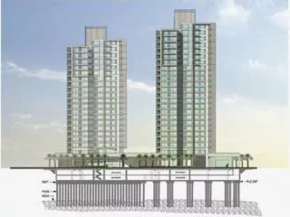
Project Description Type: Residential Building. Location: Nablus City, Bayt Wazan, behind Al-Najah National University (New Campus). Name: Al-Thuraya Residential Building. Number Of Floors: 7 floor, 2 under ground level and 5 over. Plane Area: 850 m2 for the floor.
SCOPE OF PROJECT • Select the most appropriate types of foundations for the project. • Design the selected footings. • Estimate costs of the foundations designed.
Literature Review • Foundations are the part of an engineered system to receive & transmit loads from superstructure to the underlying soil or rock . • There are two types of foundations : shallow & deep foundations. • Many factors should be taken into consideration in choosing foundation types such as soil properties , economic factors, engineering practice, ....etc
Types of footing • Isolated Footing. • Combined Footing. • Mat or Raft Foundations. • Strap or Cantilever Footings. • Pile Foundations.
Isolated Footings • Are used to support single columns. • This is one of the most economical types of footings and is used when columns are spaced at relatively long distances. • Its function is to spread the column load to the soil , so that the stress intensity is reduced .
Combined Foundations Are used in the following cases: 1) When there are two columns so close to each other & in turn the two isolated footing areas would overlap. 2) When the combined stresses are more than the allowable bearing capacity of the soil. 3) When columns are placed at the property line.
Mat or Raft Foundations • Are used to spread the load from a structure over a large area, normally the entire are of the structure . • They often needed on soft or loose soils with low bearing capacity as they can spread the loads over a larger area. • They have the advantage of reducing differential settlements.
Strap or Cantilever Footings • Cantilever footing construction uses a strap beam to connect an eccentrically loaded column foundation to the foundation of an interior column . • Are used when the allowable soil bearing capacity is high, and the distances between the columns are large .
Pile Foundations • They are long & slender members that are used to carry & transfer the load of the structure to deeper soil or rocks of high bearing capacity, when the upper soil layer are too weak to support the loads from the structure. • Piles costs more than shallow foundations; so the geotechnical engineer should know in depth the properties & conditions of the soil to decide whether piles are needed or not.
Bearing Capacity • Bearing Capacity : is the ability of a soil to support the loads applied to the ground . • Ultimate bearing capacity is the theoretical maximum pressure which can be supported without failure; • Allowable bearing capacity is the ultimate bearing capacity qu divided by a factor of safety (F.S).
Settlement • When building structures on top of soils, one needs to have some knowledge of how settlement occurs & how fast settlement will occur in a given situation. • So, There are three types of settlement: 1. Initial settlement 2. Primary settlement 3. Secondary settlement
Settlement (Cont.) • Total Settlement = SI + SC + SS • The allowable bearing capacity and the type of foundations provided later are evaluated based on the settlements limits. This means that the settlement of the proposed foundation would be within the acceptable limits if the allowable bearing capacity provided is used.
Geotechnical Investigation • The area which we studied not in the same elevations. The general soil formation is Gray to white, weathered, high limestone formation covered by brown silty clay, boulders and vegetation. Occasional pockets filled with soil are expected within the rock formation.
laboratory test results: Unit weight of the soil = 18 KN/m3 Cohesion (C) = 30 Angle of Internal Friction (φ) = 15
Structuraldesign Column loads are calculated using (sap program), the structure subjected to the following loads: 1) Dead Load (own weight). 2) Super imposed dead load =350 kg/m2. 3) Live load =250 kg/m2. Using ACI code, the ultimate loads are calculated considering load combination : Pu =1.2Dead + 1.6Live. Material characteristics used in this project are: f’c=300kg/cm2 (B 300) Where: f’c is the compressive strength of concrete fy = 4200 kg/cm2 Where: fy is the yield strength of steel
Isolated and CombinedFootingDesign • Manual Design steps: • Area of footing = Total service loads on column / net soil pressure • Determine footing dimensions B & H . • Assume depth for footing. • Check soil pressure. • Check wide beam shear : Vc > Vult • Check punching shear : Vcp > Pult, punching • Determine reinforcement steel in the two directions. • Check development length .
THICKNESSES OF FOOTINGS Depth of footing will be controlled by wide beam shear and punching shear. Wide Beam Shear: Shear cracks are form at distance “d” from the face of column, and extend to the compression zone, the compression zone will be fails due to combination of compression and shear stress. Punching Shear: Formation of inclined cracks around the perimeter of the concentrated load may cause failure of footing. Max, formation of these cracks occurred at distance “d\2” from each face of he column.
Steel reinforcement : • Isolated footing represented as cantilever, so the max moment occurs at the face of the column: • Ultimate moment at the face of the column • (Mult) =(qult*ln2)/2 • Mn =Mu\Φ , where, Φ=0.9 • ρ =0.85 f˜c / fy (1 – 1 – (2.61* 106 * Mu / b d2 f˜c ) ) • WHERE • ρ: Steel ratio • As = ρbd
Example for Single FootingFooting 1: "C14“ Slab area = 17.22 m2 Beams area = 11.7 m2 Columns section area = 0.25 m2 Slab weight= Area * DL =87.82 KN Beams weight = Area * Thickness * Density =87.75 KN Column weight = Area * Height * Density= 18.75 KN
For One Store : Service dead Load = ∑ Load = 194.32 KN Service Live Load = Tarea * 2.5 = 72.3 KN For seven Stores PD= 194.32 * 7 = 1360.24 KN PL = 72.3 * 7 = 506.1 KN f˜c = 30 Mpa fy = 420 Mpa qall = 200 KN/ m2
Solution Steps 1) Determine the dimensions: Af = Pa/ qall = 9.33 m2 A= B * L L = 3.5 m , B = 2.8 m New Area = 9.8m22) Calculate d from wide beam shear: Vu = qu (L – d) qall = Pu / Af = 249.2 KN/m2 Vu = 249.2 (1.15 – d) øVc= (0.75) (1/6) ( 30 ) (1000) (d) = 684.65 d But; øVc = Vu 684.65 d = 286.6 – 249.2 d d = 0.30 m
3) Check Punching Shear: Ao = b1 * b2 b1 = c1 + 2(d/2) = 0.8m Ao = (0.8*0.8) = 0.64 m2 Vup = Pu - quAo = 2441 KNøVup = 1301.4 KN So;Vup > øVcp …….. This is Not Ok
Try d = 0.40 mThen; Ao = 0.81 m2 Bo = 3.6 m Vup = 2398.6 KN øVcp = 1952.1 KN ……. Not Ok d = 0.50 m Vup = 2351.3 KN Vcp = 2711.23 KN L = 3.5m B = 2.8m d= 0.5m h = 0.55m
4) Design for Flexure: Mu = qul2 / 2 = 164.8 KN.m ρ = 0.00177 As= ρ b d = 885mm2 Asmin = 0.0018 b = 990 mm2 As < Asmin …….. Not Ok Use Asmin = 990 mm2= 5 ø 16/m In each direction
5) Check Development Length: L – cover = 1.15 – 0.08 = 1.07 Ldt = 0.48 (420) * 16 / (30) = 0.59 L- cover = 1.07 > L dt = 0.59 It is Ok no need for Hook.Figure in the next slide illustrate the details of the footing reinforcements of F14
Example for combined Footing Weights on A2 : Slab weight = 11.3 KN Beam's weight = 20.97 KN Column weight = 15.75 KN ∑Dead Load = 48.02 KN Live Load = 12.52 KN Total load: PD = 336.14 KN PL = 87.64 KN
Loads on column B1 : Slab Area = 9.66 m2 Beam Area = 6.961 m2 Column section area = 0.24m2Weights on B1 : Slab weight = 49.3 KN Beam weight = 52.21 KN Column weight = 18 KN ∑ Load = 119.51 KN Live Load = 41.55 KNTotal loads : PD = 836.57 KN PL = 290.85 KN
Solution Steps 1) Determine the dimensions:Af = ∑ Q / qall = 7.76m2L = 4.2 m B = 1.9m 2) Calculate d from wide beam shear: Pu1 = 543.6 KN Pu2 = 1469.24 KN Avg. Load factor = ∑Pu / ∑Pa = 1.3 Pu1 Modified = 1.3 (Q1) = 551KN Pu2 Modified = 1.3 (Q2) = 1465.65 KN qu = ( Pu1 (mod) + Pu2 (mod) ) / L = 480.15 KN/m Vu = 552.3 – 480.15 d ………………………………(a) ØVc = 1300.8 d ….…………………………..(b) d = 0.31 m, Use (d = 0.35 m)
3) Check Punching Shear : For Left Column : Ao = 0.6825m2 bo = 3.4 m For Right Column : Ao = 0.7475 m2 bo = 3.6 m Check for Left Column: Vup = Pu – quAo = 223.3 KN øVcp = 1613.2 KN øVcp > Vup ……………… Ok Check For Right Column : Vup = 1106.74 KN øVcp = 1708.1 KN øVcp > Vup …………………..Ok
4) Design For Flexure :Because of all negative moments we will use Asmin for all Footings; Asmin = 0.0033 (1900) (400 ) = 2508 mm2 Use 4ø 16 /m For Left Column : Mu = qul2 / 2 qu = Pu1 / ( B * b1) = 446.2 KN/m Mu = 55.8 KN.m/m ρ = 0.00122 < 0.0018Take; Asmin = 0.0018 ( 650 ) ( 400) = 468 mm2 …. Use 4 ø 16 /m
For Right Column : qu = Pu2 / ( B * b3 ) = 671 KN/m Mu = 188.7 KN.m ρ = 0.00422 As = ρ b d = 1698.55 mm2 ….. Use 4 ø 16 /m S =( 1000 ) / [(0.0018)(1000)(400)/201]= 279 mm ….. take S = 250 mm
Figure below illustrate the details of the footing reinforcements of combined footing
Table Below Shows the Details & The Reinforcements of the Single & Combined Footings
Quantities and Cost Estimations This slides presents the quantities and cost estimations of all geotechnical elements that are used in this project. The activities studied at this project include the following: site investigation, excavation, planning, soil improvements, frame work, concrete and reinforcement. Primavera software is used to schedule the above activities. In addition to that the cost estimates for each activity is done and also presented.
Table below shows the geotechnical activities that are incorporated in this project. The table shows the activity identification (activity ID), activity name, and activity original duration in days.
Scheduling the Geotechnical ActivitiesPrimavera software is used to scheduling the geotechnical activities and the dependency between various activities. These activities and their scheduling are illustrated in the next Figure.
Cost EstimatesThe materials and the activities costs of this project are calculated in Dollars .The table below shows each item and it’s cost .