Download
1 / 7
230 likes | 746 Views
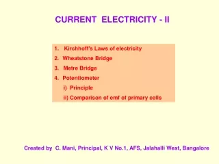
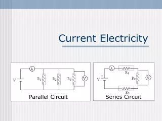
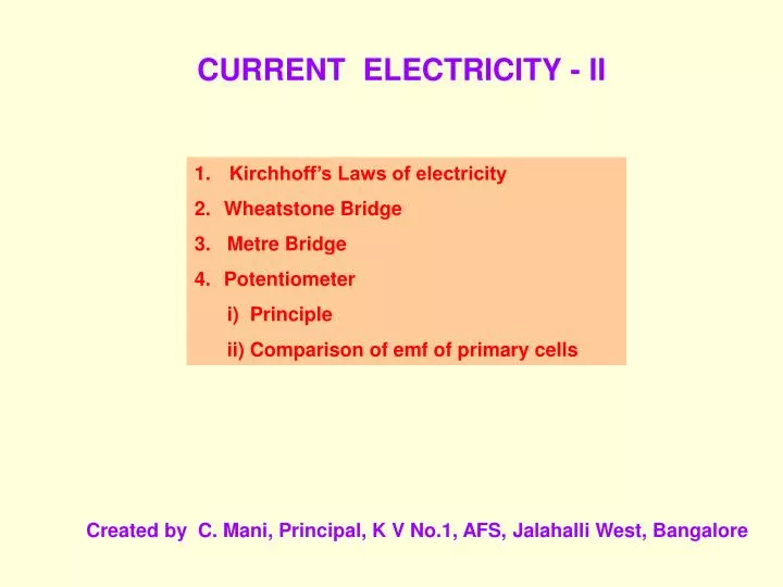
CURRENT ELECTRICITY - II. Kirchhoff’s Laws of electricity Wheatstone Bridge 3. Metre Bridge Potentiometer i) Principle ii) Comparison of emf of primary cells. Created by C. Mani, Principal, K V No.1, AFS, Jalahalli West, Bangalore. I 2. I 1. I 3.

E N D
CURRENT ELECTRICITY - II • Kirchhoff’s Laws of electricity • Wheatstone Bridge • 3. Metre Bridge • Potentiometer • i) Principle • ii) Comparison of emf of primary cells Created by C. Mani, Principal, K V No.1, AFS, Jalahalli West, Bangalore
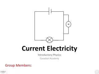
I2 I1 I3 I1 - I2 - I3 + I4 - I5 = 0 I5 I4 KIRCHHOFF’S LAWS: I Law or Current Law or Junction Rule: The algebraic sum of electric currents at a junction in any electrical network is always zero. O • Sign Conventions: • The incoming currents towards the junction are taken positive. • The outgoing currents away from the junction are taken negative. Note: The charges cannot accumulate at a junction. The number of charges that arrive at a junction in a given time must leave in the same time in accordance with conservation of charges.
II Law or Voltage Law or Loop Rule: E1 I1 I1 R1 A B Loop ABCA: - E1 + I1.R1 + (I1 + I2).R2 = 0 Loop ACDA: - (I1 + I2).R2-I2.R3 + E2 = 0 R2 I2 I1 + I2 I1 C D R3 I2 I2 E2 Note: The path can be traversed in clockwise or anticlockwise direction of the loop. The algebraic sum of all the potential drops and emf’s along any closed path in an electrical network is always zero. • Sign Conventions: • The emf is taken negative when we traverse from positive to negative terminal of the cell through the electrolyte. • The emf is taken positive when we traverse from negative to positive terminal of the cell through the electrolyte. • The potential falls along the direction of current in a current path • and it rises along the direction opposite to the current path. • The potential fall is taken negative. • The potential rise is taken positive.
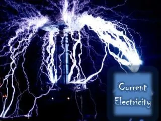
B P Q I1 I1 - Ig Ig A G C S R I - I1 I I - I1 +Ig I D I I E P R Q S Wheatstone Bridge: Currents through the arms are assumed by applying Kirchhoff’s Junction Rule. Applying Kirchhoff’s Loop Rule for: • Loop ABDA: • I1.P - Ig.G + (I - I1).R = 0 Loop BCDB: - (I1 - Ig).Q + (I - I1 + Ig).S + Ig.G = 0 When Ig = 0, the bridge is said to balanced. By manipulating the above equations, we get
R.B (R) X G A B J K E R l X 100 - l R RAJ X RJB R AJ X JB Metre Bridge: Metre Bridge is based on the principle of Wheatstone Bridge. l cm 100 - l cm When the galvanometer current is made zero by adjusting the jockey position on the metre-bridge wire for the given values of known and unknown resistances, (Since, Resistance α length) Therefore, X = R (100 – l)∕l
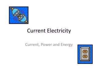
I + V E A 0 J 100 A 200 + 300 Rh B 400 K V 0 l Potentiometer: Principle: V = I R = I ρl/A If the constant current flows through the potentiometer wire of uniform cross sectional area (A) and uniform composition of material (ρ), then V = Kl or V αl l cm V /l is a constant. The potential difference across any length of a wire of uniform cross-section and uniform composition is proportional to its length when a constant current flows through it.
I E1 R.B + G + E A E2 A 0 J2 l2 100 + J1 200 Rh B 300 400 K Comparison of emf’s using Potentiometer: The balance point is obtained for the cell when the potential at a point on the potentiometer wire is equal and opposite to the emf of the cell. l1 E1 = VAJ1 = I ρl1 /A E2 = VAJ2 = I ρl2 /A E1/ E2 = l1/l2 Note: The balance point will not be obtained on the potentiometer wire if the fall of potential along the potentiometer wire is less than the emf of the cell to be measured. The working of the potentiometer is based on null deflection method. So the resistance of the wire becomes infinite. Thus potentiometer can be regarded as an ideal voltmeter. End of Current Electricity