Download
1 / 98
990 likes | 1.03k Views
Chapter. Current Electricity. 22. Chapter. Current Electricity. 22. In this chapter you will:. Explain energy transfer in circuits. Solve problems involving current, potential difference, and resistance. Diagram simple electric circuits. Chapter. Table of Contents. 22.

E N D
Chapter Current Electricity 22
Chapter Current Electricity 22 In this chapter you will: • Explain energy transfer in circuits. • Solve problems involving current, potential difference, and resistance. • Diagram simple electric circuits.
Chapter Table of Contents 22 Chapter 22: Current Electricity Section 22.1: Current and Circuits Section 22.2: Using Electric Energy
Section Current and Circuits 22.1 In this section you will: • Describe conditions that create current in an electric circuit. • Explain Ohm’s law. • Design closed circuits. • Differentiate between power and energy in an electric circuit.
Section Current and Circuits 22.1 Producing Electric Current • Flowing water at the top of a waterfall has both potential and kinetic energy. • However, the large amount of natural potential and kinetic energy available from resources such as Niagara Falls are of little use to people or manufacturers who are 100 km away, unless that energy can be transported efficiently. • Electric energy provides the means to transfer large quantities of energy over great distances with little loss.
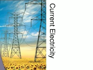
Section Current and Circuits 22.1 Producing Electric Current • This transfer usually is done at high potential differences through power lines. • Once this energy reaches the consumer, it can easily be converted into another form or combination of forms, including sound, light, thermal energy, and motion. • Because electric energy can so easily be changed into other forms, it has become indispensable in our daily lives.
Section Current and Circuits 22.1 Producing Electric Current • When two conducting spheres touch, charges flow from the sphere at a higher potential to the one at a lower potential. • The flow continues until there is no potential difference between the two spheres. • A flow of charged particles is an electric current.
Section Current and Circuits 22.1 Producing Electric Current • In the figure, two conductors, A and B, are connected by a wire conductor, C. • Charges flow from the higher potential difference of B to A through C. • This flow of positive charge is called conventional current. • The flow stops when the potential difference between A, B, and C is zero.
Section Current and Circuits 22.1 Producing Electric Current • You could maintain the electric potential difference between B and A by pumping charged particles from A back to B, as illustrated in the figure. • Since the pump increases the electric potential energy of the charges, it requires an external energy source to run. • This energy could come from a variety of sources.
Section Current and Circuits 22.1 Producing Electric Current • One familiar source, a voltaic or galvanic cell (a common dry cell), converts chemical energy to electric energy. • A battery is made up of several galvanic cells connected together. • A second source of electric energy— a photovoltaic cell, or solar cell—changes light energy into electric energy.
Section Current and Circuits 22.1 Electric Circuits • The charges in the figure move around a closed loop, cycling from pump B, through C to A, and back to the pump. • Any closed loop or conducting path allowing electric charges to flow is called an electric circuit. • A circuit includes a charge pump, which increases the potential energy of the charges flowing from A to B, and a device that reduces the potential energy of the charges flowing from B to A.
Section Current and Circuits 22.1 Electric Circuits • The potential energy lost by the charges, qV, moving through the device is usually converted into some other form of energy. • For example, electric energy is converted to kinetic energy by a motor, to light energy by a lamp, and to thermal energy by a heater. • A charge pump creates the flow of charged particles that make up a current.
Section Current and Circuits 22.1 Electric Circuits Click image to view the movie.
Section Current and Circuits 22.1 Conservation of Charge • Charges cannot be created or destroyed, but they can be separated. • Thus, the total amount of charge—the number of negative electrons and positive ions—in the circuit does not change. • If one coulomb flows through the generator in 1 s, then one coulomb also will flow through the motor in 1 s. • Thus, charge is a conserved quantity.
Section Current and Circuits 22.1 Conservation of Charge • Energy also is conserved. • The change in electric energy, ΔE, equals qV. Because q is conserved, the net change in potential energy of the charges going completely around the circuit must be zero. • The increase in potential difference produced by the generator equals the decrease in potential difference across the motor.
Section Current and Circuits 22.1 Rates of Charge Flow and Energy Transfer • Power, which is defined in watts, W, measures the rate at which energy is transferred. • If a generator transfers 1 J of kinetic energy to electric energy each second, it is transferring energy at the rate of 1 J/s, or 1 W. • The energy carried by an electric current depends on the charge transferred, q, and the potential difference across which it moves, V. Thus, E =qV.
Section Current and Circuits 22.1 Rates of Charge Flow and Energy Transfer • The unit for the quantity of electric charge is the coulomb. • The rate of flow of electric charge, q/t, called electric current, is measured in coulombs per second. • Electric current is represented by I, so I =q/t. • A flow of 1 C/s is called an ampere,A.
Section Current and Circuits 22.1 Rates of Charge Flow and Energy Transfer • The energy carried by an electric current is related to the voltage, E =qV. • Since current, I = q/t, is the rate of charge flow, the power, P =E/t, of an electric device can be determined by multiplying voltage and current. • To derive the familiar form of the equation for the power delivered to an electric device, you can use P = E/t and substitute E = qV and q = It PowerP= IV • Power is equal to the current times the potential difference.
Section Current and Circuits 22.1 Resistance and Ohm’s Law • Suppose two conductors have a potential difference between them. • If they are connected with a copper rod, a large current is created. • On the other hand, putting a glass rod between them creates almost no current. • The property determining how much current will flow is called resistance.
Section Current and Circuits 22.1 Resistance and Ohm’s Law • The table below lists some of the factors that impact resistance.
Resistance Section Current and Circuits 22.1 Resistance and Ohm’s Law • Resistance is measured by placing a potential difference across a conductor and dividing the voltage by the current. • The resistance, R, is defined as the ratio of electric potential difference, V, to the current, I. • Resistance is equal to voltage divided by current.
Section Current and Circuits 22.1 Resistance and Ohm’s Law • The resistance of the conductor, R, is measured in ohms. • One ohm (1 Ω ) is the resistance permitting an electric charge of 1 A to flow when a potential difference of 1 V is applied across the resistance. • A simple circuit relating resistance, current, and voltage is shown in the figure.
Section Current and Circuits 22.1 Resistance and Ohm’s Law • A 12-V car battery is connected to one of the car’s 3-Ω brake lights. • The circuit is completed by a connection to an ammeter, which is a device that measures current. • The current carrying the energy to the lights will measure 4 A.
Section Current and Circuits 22.1 Resistance and Ohm’s Law • The unit for resistance is named for German scientist Georg Simon Ohm, who found that the ratio of potential difference to current is constant for a given conductor. • The resistance for most conductors does not vary as the magnitude or direction of the potential applied to it changes. • A device having constant resistance independent of the potential difference obeys Ohm’s law.
Section Current and Circuits 22.1 Resistance and Ohm’s Law • Most metallic conductors obey Ohm’s law, at least over a limited range of voltages. • Many important devices, such as transistors and diodes in radios and pocket calculators, and lightbulbs do not obey Ohm’s law. • Wires used to connect electric devices have low resistance. • A 1-m length of a typical wire used in physics labs has a resistance of about 0.03 Ω.
Section Current and Circuits 22.1 Resistance and Ohm’s Law • Because wires have so little resistance, there is almost no potential drop across them. • To produce greater potential drops, a large resistance concentrated into a small volume is necessary. • A resistor is a device designed to have a specific resistance. • Resistors may be made of graphite, semiconductors, or wires that are long and thin.
Section Current and Circuits 22.1 Resistance and Ohm’s Law • There are two ways to control the current in a circuit. • Because I =V/R, I can be changed by varying V, R, or both. • The figure a shows a simple circuit. • When V is 6 V and R is 30 Ω, the current is 0.2 A.
Section Current and Circuits 22.1 Resistance and Ohm’s Law • How could the current be reduced to 0.1 A? According to Ohm’s law, the greater the voltage placed across a resistor, the larger the current passing through it. • If the current through a resistor is cut in half, the potential difference also is cut in half.
Section Current and Circuits 22.1 Resistance and Ohm’s Law • In the first figure,the voltage applied across the resistor is reduced from 6 V to 3 V to reduce the current to 0.1 A. • A second way to reduce the current to 0.1 A is to replace the 30-Ω resistor with a 60-Ω resistor, as shown in the second figure.
Section Current and Circuits 22.1 Resistance and Ohm’s Law • Resistors often are used to control the current in circuits or parts of circuits. • Sometimes, a smooth, continuous variation of the current is desired. • For example, the speed control on some electric motors allows continuous, rather than step-by-step, changes in the rotation of the motor.
Section Current and Circuits 22.1 Resistance and Ohm’s Law • To achieve this kind of control, a variable resistor, called a potentiometer, is used. • A circuit containing a potentiometer is shown in the figure.
Section Current and Circuits 22.1 Resistance and Ohm’s Law • Some variable resistors consist of a coil of resistance wire and a sliding contact point. • Moving the contact point to various positions along the coil varies the amount of wire in the circuit. • As more wire is placed in the circuit, the resistance of the circuit increases; thus, the current changes in accordance with the equation I = V/R.
Section Current and Circuits 22.1 Resistance and Ohm’s Law • In this way, the speed of a motor can be adjusted from fast, with little wire in the circuit, to slow, with a lot of wire in the circuit. • Other examples of using variable resistors to adjust the levels of electrical energy can be found on the front of a TV: the volume, brightness, contrast, tone, and hue controls are all variable resistors.
Section Current and Circuits 22.1 The Human Body • The human body acts as a variable resistor. • When dry, skin’s resistance is high enough to keep currents that are produced by small and moderate voltages low. • If skin becomes wet, however, its resistance is lower, and the electric current can rise to dangerous levels. • A current as low as 1 mA can be felt as a mild shock, while currents of 15 mA can cause loss of muscle control, and currents of 100 mA can cause death.
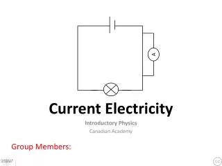
Section Current and Circuits 22.1 Diagramming Circuits • An electric circuit is drawn using standard symbols for the circuit elements. • Such a diagram is called a circuit schematic. Some of the symbols used in circuit schematics are shown below.
Section Current and Circuits 22.1 Current Through a Resistor A 30.0-V battery is connected to a 10.0-Ω resistor. What is the current in the circuit?
Section Current and Circuits 22.1 Current Through a Resistor Step 1:Analyze and Sketch the Problem
Section Current and Circuits 22.1 Current Through a Resistor Draw a circuit containing a battery, an ammeter, and a resistor.
Section Current and Circuits 22.1 Current Through a Resistor Show the direction of the conventional current.
Section Current and Circuits 22.1 Current Through a Resistor Identify the known and unknown variables. Known: V = 30.0 V R = 10 Ω Unknown: I = ?
Section Current and Circuits 22.1 Current Through a Resistor Step 2:Solve for the Unknown
Section Current and Circuits 22.1 Current Through a Resistor Use I = V/R to determine the current.
Section Current and Circuits 22.1 Current Through a Resistor Substitute V = 30.0 V, R = 10.0 Ω
Section Current and Circuits 22.1 Current Through a Resistor Step 3:Evaluate the Answer
Section Current and Circuits 22.1 Current Through a Resistor • Are the units correct? Current is measured in amperes. • Is the magnitude realistic? There is a fairly large voltage and a small resistance, so a current of 3.00 A is reasonable.
Section Current and Circuits 22.1 Current Through a Resistor • Step 1:Analyze and Sketch the Problem • Draw a circuit containing a battery, an ammeter, and a resistor. • Show the direction of the conventional current. The steps covered were:
Section Current and Circuits 22.1 Current Through a Resistor • Step 2:Solve for the Unknown • Use I = V/R to determine the current. • Step 3:Evaluate the Answer The steps covered were:
Section Current and Circuits 22.1 Diagramming Circuits • An artist’s drawing and a schematic of the same circuit are shown below. • Notice in both the drawing and the schematic that the electric charge is shown flowing out of the positive terminal of the battery.
Section Current and Circuits 22.1 Diagramming Circuits • An ammeter measures current and a voltmeter measures potential differences. • Each instrument has two terminals, usually labeled + and –. A voltmeter measures the potential difference across any component of a circuit. • When connecting the voltmeter in a circuit, always connect the + terminal to the end of the circuit component that is closer to the positive terminal of the battery, and connect the – terminal to the other side of the component.
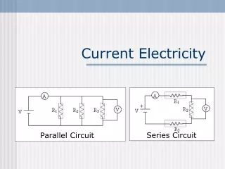
Section Current and Circuits 22.1 Diagramming Circuits • When a voltmeter is connected across another component, it is called a parallel connection because the circuit component and the voltmeter are aligned parallel to each other in the circuit, as diagrammed in the figure. • Any time the current has two or more paths to follow, the connection is labeled parallel. • The potential difference across the voltmeter is equal to the potential difference across the circuit element. • Always associate the words voltage across with a parallel connection.