Download

1 / 35
370 likes | 375 Views
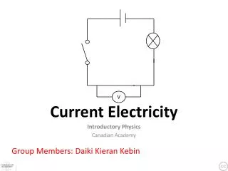
Current Electricity. Continuous motion of charged particles through a potential /voltage difference. Potential Dif/Voltage induces charges to move. Amount of work per charge. Two models for current. Conventional current – positive charges in motion (IB).

E N D
Current Electricity Continuous motion of charged particles through a potential /voltage difference.
Potential Dif/Voltage induces charges to move. Amount of work per charge.
Two models for current. • Conventional current – positive charges in motion (IB). • Real/electron current – electrons in motion.
Voltage gives free e- a push -charges gain lose PE and gain KE:DPE = KEqV =1/2 mv2.
Units of Current - FundamentalAmperes (A) measures rate of charge flow in q/t. 1 A = 1 C/s passing a point or cross section of wire.
Ex 1. How many e- must pass a point in a wire every second to carry a current of 2 A? • 2 C/s x 1.6 x 10⁻¹⁹ C/e- = 1.25 x 10¹⁹ e-.
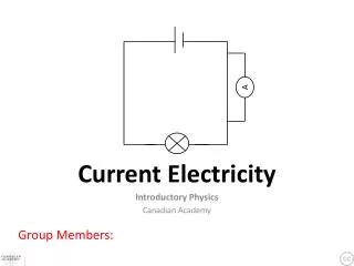
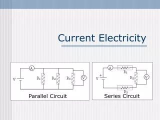
To get continuous flow of charge:1. Voltage (EMF) source = to do work on q which gains E. Batteries, generators, solar cells. The source raises the PE of charges.2. Closed Circuit – continuous pathway for charges to flow –metal wire, ionic solutions.4. Resistors/Load – device to convert/dissipate energy (so that source is not immediately discharged). Resistors lower the PE of charges.
How it happens P. D. Causes electricfield to spread through wire at near light speed. All e- in wire respond by moving in field & colliding with neighboring e- starting to flow. Drift velocity is net speed in one direction. It’s slow for e- (mm/s).
Electric field in wire caused by voltage source induces e- to move through.
Resistors, Appliances, Loads Bulbs, toasters, etc. convert Eelc to other forms– heat, light etc.These cause the e- to lose PE. Devices are called resistors or loads. They slow down the e- through collisions so they resist current flow.
Direct Current (DC) circuits have current flow of e- in 1 direction frEnvisioned as traveling from the neg to + terminal of battery.Conventional current (pos charge) fr pos to neg..
Resistance Caused by internal collisions/interactions. Ratio of Voltage to Current R = V/I Units ohms W. V/A
Resistance Occurs in wires as well as appliances. Certain factors affect how much resistance a wire will offer to current flow.
Factors affecting wire resistance. • 1. Length • 2. Area • 3. Temperature • 4. Type of material
Length – longer wire offers more resistance. More chances for friction in wire. Less resistance More resistance
At a given temperature, R = resistancer = constant of resistivityl = length A = cross sectional areaSee table
Potential Drop If a current flows in a resistor or appliance, there must be a pd across the ends of the resistor. The voltage pushes the charge. The resistor “drops” or lowers the PE of the charge. So is sometimes called potential drop. - + R e- current
Ohm’s Law When temperature across a metallic resistor is constant, the current is directly proportional to pd across it. V = IR V/I = R = constant. V = volts J/C I = current A, C/s R = total resistance ohm’s W.
V = RI yield direct linear relationship.V on Y axis. I on x axis. R is slope of straight line. R = constant. Switch axis 1/R is slope.
I V Light bulbheats up as current goes through.Watch axis - R is 1/slope here.
When a graph shows non-ohmic behavior, you can simply find R = V/I at a point – don’t use slope. 0.2 V/1.5 x 10-3 A R = 133.3 W.
Film Clips Resistance 10 mim http://www.youtube.com/watch?v=YGvu9iqjJq4 • Film Clip Voltage 8.5 min • http://www.youtube.com/watch?v=F1p3fgbDnkY&feature=relmfu
Power in Resistors Resistors/loads convert EElc to other forms. P is rate E used/converted/dissipated or supplied J/s or Watts. Power rating of 500 W means Eelc converted to other kinds at rate 500 J/s.
P = W. = Vq. = VI t t P = VI The power is rate thermal E dissipated & work done in resistor.
Other Power Equations For devices that obey Ohm’s Law we use R = V/I to derive other equations for power. P = RI2 = V2. R
Graphs P=VI Slope = Voltage Power Current
Power Ratings for Appliances Devices are rated by the power they use. A bulb rated 60 W 220 V means: the bulb will dissipate 60 W when attached to a 220 p.d. If a different p.d. is used, then it won’t dissipate 60 W.
Fuses As current flows, wires heat up. Fuses designed to break circuit if current becomes to high for the wires. Fuse should be rated just above the ideal operating current for a circuit.
Kilowatt hours kWh. • Power is a rate of energy use. • Electric sold in kWh which is Pt = Energy. • 1 kWh is energy delivered to home in 1hour. • 1 kWh (1000 W/kW)(60 min/h)(60s/min) = 3.6 x 10⁶ Ws = 3.6 x 10⁶ J
Film Clip Resistance • http://www.youtube.com/watch?v=YGvu9iqjJq4&NR=1 IB Packet and Kerr Pg 135 #3, 4, 17, 21.