Download
1 / 28
300 likes | 449 Views
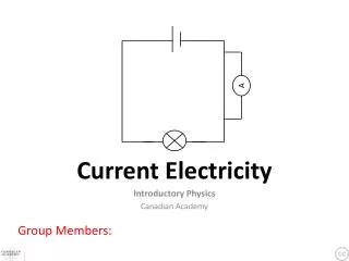
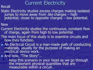
Current Electricity. Current Electricty. Unlike Static electricity which does not flow, Current electricity “flows” through a circuit.

E N D
Current Electricty • Unlike Static electricity which does not flow, Current electricity “flows” through a circuit. • The electrons flow from the negative pole to the positive pole. There has to be something that forces the electrons back to the negative pole so that they can flow again. This is what a battery or generator does.
Current Electricity Electrons are negatively charged and flow from the negative pole to the positive. A battery (or generator) pushes the electrons back to the negative pole so that they can flow to the positive. The greater the difference between these two poles, the greater the Electrical Potential Difference.
Current Electricity • Voltage is the potential difference between the Positive and Negative Poles. • The greater the difference, the greater the voltage and the more work that it can do. • As electricity flows through a circuit, the voltage “drops” at each resistor until it equals zero at the end of the circuit. • The battery (or generator) raises the voltage to the original volts and the electricity flows through the circuit again.
Current Electricity - + 1.5 V V = 0 V V = 1.5 V
Current Electricity • Amperage is the “rate of flow” of the electrons • The higher the amperage of a circuit, the faster the electrons are “flowing” • 1 Amp = 1 Coulomb/sec. • The symbol for amperage is I • The unit for amperage is amps. • There are two factors that determine the amperage of a circuit: • The resistance to the flow of electrons. • The voltage, or the electric potential.
Current Electricity • Resistance is as the name implies, something that resists the “flow” of electrons • Anything that uses electricity is a resistor • Resistance is measured in ohms ()
Ohm’s Law • Relates the three components of a circuit • Amperage = Voltage/ Resistance • I = V/R • or V = I R
Simple Circuits(only one path) A amp meter
Simple Circuits(only one path) amp meter A What is the current at A if there is 12 Volts and the light bulb has 0.5 of resistance? I = V/R , I = 12 V/0.5 , I = 24 Amps
Simple Circuit R1 120V 15 Amps What is the resistance of the light bulb (R1) if there is 120 Volts and the current is 15 Amps? R = V/I R = 120V/15A R = 8
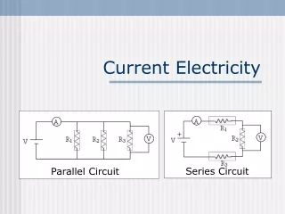
Series Circuits In a Series Circuit, there are more than one resistor, but there is only one path. for the electrons to follow.
Series Circuits Before you can solve for voltage or current, you need to know the total resistance of the Circuit RT = R1+R2 + R3 …. I = V/ RT
Series Circuits 15 10 15 24 V A Find RT RT= 15 + 10 + 15 RT = 40 I = V/R I = 24V/40 I = 0.6 A
Parallel Circuits In a parallel circuit, there are more than one path for the electrons to follow. You have to calculate what the equivalent resistance would be. In other words, what one resistor would have the same value as the three resistors in the circuit.
Parallel Circuits Since there are more than one path, the current actual increases as more paths are added. The total resistance is an inverse relationship. As resistors are added, the total resistance decreases.
Parallel Circuits R1 = 30 R2 = 15 R3 = 15 120V Equivalent Resistance = 1 = 1 + 1 + 1 …… RT R1 R2 R3 • = 1 + 1 + 1 = 5 • RT 30 15 15 30 • Equivalent R = 30 = 6 • 5
Parallel Circuits 6 A 120 V The 3 resistors are replaced by the equivalent resistor of 6 . Now you can calculate the current in the circuit.
Parallel Circuits R1 = 30 R2 = 15 R3 = 15 120 V A Equivalent Resistance = 6 I = V/RT I = 120 V / 6 I = 20 Amps
Combined Circuits A R5 75
A R5 75 • In a combined circuit problem, you first have to find all of the equivalent • resistances in the parallel portions. • 1 = 1 + 1 = 7 500 = 71.42 • R1+2 100 250 500 7 • 1 = 1 + 1 = 4 + 7 1400 = 127.27 • R3 +4 350 200 1400 1400 11
A R5 75 Now that the parallel portions have been replaced by their equivalents, you treat the circuit as a series circuit and find the total resistance. RT = 71.429 + 127.27 + 75 = 273.70 I = V/R I = 24 V / 273.70 I = 0.088 Amps This is the current in the entire circuit, not the current in the parallel portions.
24 V A 273.70 Now that the parallel portions have been replaced by their equivalents, you treat the circuit as a series circuit and find the total resistance. RT = 71.429 + 127.27 + 75 = 273.70 I = V/R I = 24 V / 273.70 I = 0.088 Amps This is the current in the entire circuit, not the current in the parallel portions.
Finding Voltage Drops V1 V2 R5 75 V3 Find the voltage drops at each meter.
Voltage Drops To find the voltage drops in a parallel portion, you use the Equivalent resistance of that portion and the current for the entire circuit. V1 = I x R1+2 = (0.088 A)(71.42 V) = 6.28 V V2 = I x R3 + 4 = (0.088 A)(127.27 V) = 11.20 V V3 = I x R5 = (0.088 A)(75 ) = 6.6 V All of the voltage drops should equal the 24.08 V total voltage of the circuit
Current in Parallel Portions A2 A3 A1 A4 A5 R5 75
Current in Parallel Portions The current in the parallel portions is not the same as in the main circuit. It gets divided depending on the actual resistor ( not the equivalent). You need to know the voltage drop at each resistor before you can calculate the current. A1 = is the current in the main portion = 0.088 Amps A2 = V1 / R1 = 6.28 V/ 100 = 0.0628 Amps A3 = V1/R2 = 6.28 V / 250 = 0.0251 Amps (It should equal the total amps) 0.08792 Amps A4 = V2/ R3 = 11.2 V/ 350 = 0.032 Amps A5 = V2/ R4 = 11.2 V/ 200 = 0.056 Amps (It should equal the total amps) 0.088 Amps