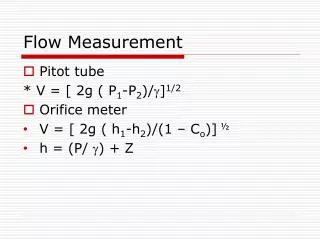
Download
1 / 34
350 likes | 567 Views
TSF Timer Freq. Management and Measurement Procedure (TFM 2 P) . Authors:. Date: 2012-11-13. Abstract. The detailed three procedures of enhanced power saving function which employs the proposed TFM 2 P (TSF timer Frequency Management & Measurement Procedure) is presented.

E N D
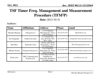
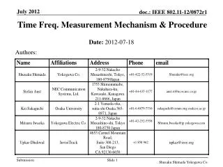
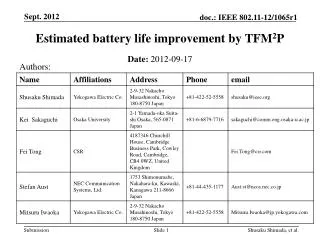
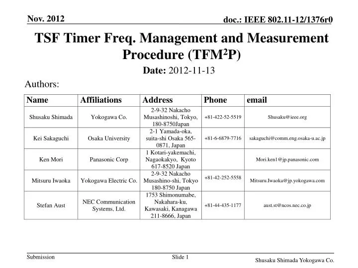
TSF TimerFreq. Management and Measurement Procedure (TFM2P) Authors: • Date:2012-11-13 Shusaku Shimada Yokogawa Co.
Abstract • The detailed three procedures of enhancedpower saving function which employs the proposed TFM2P (TSF timer FrequencyManagement & Measurement Procedure) is presented. • TFM2P can be used with existing Power Saving mechanisms to allow STA waking up precisely and sleeping longer, and some sort of access control mechanisms for following operational conditions; • numerous numbers of sensors or meters, with lower traffic at each STA, requiring battery conservation. (use case 1a/c/d/e/f) • access control numerous numbers of sensors or meters using wake-up timing control schemes by TSF timer synchronization, rather than simple ALOHA. (RAW, TWT, PS-mode, etc.) Shusaku Shimada Yokogawa Co.
Principle of PS feature • Synchronize peer nodes to TSF • Schedule or Trigger for STA wake-up • Sleep as long as possible for peer nodes to queue • Awake as short as possible to communicate quickly • Accuracy of TSF sync does set the duty ratio , due to wake-up margin. • ; for small • c.f. Peer to peer clock frequency accuracy=40ppm, • (1) = (36ms / 15min) + 40 = 40 + 40 ppm • (2) = (360us / hour) + 40 = 0.1 + 40 ppm or = (3.6ms / 10 hour) +40= 0.1 +40 ppm Shusaku Shimada Yokogawa Co.
Wake-up synchronization Simple AP announcement of TSF accuracy (1) • Wake-up Timing margin depends on TSF timer freq. accuracy △; TS TW (IEEE802.11-2012) Tolerance ±100ppm scheduled wake-up time (ideal case) AP (e.g. TSF master) ± △· (TW –TS) • Wake-up margin-△· (TW – TS) TW notified ≈ STA (e.g. TSF slave) actual sleep duration sleep again STA awake △ includes accuracy of both AP & STA • < 11-12/130r0 “Beacon Reception of Long Sleeper” > • AP is supposed to announce TSF accuracy △, (△<100ppm) • STA is able to wake up at (TW –TS)(1 - △) +TS • TS : TSF timer value just after last time it was synchronized Shusaku Shimada Yokogawa Co.
Wake-up synchronization Simple AP announcement of TSF accuracy (2) • Awake period of STA may become much longer than actual • Communication. TW scheduled wake-up time (ideal case) AP (e.g. TSF master) • ± △· (TW –TS) actual communication • Wake-up margin -△· (TW –TS) TW notified ≈ STA (e.g. TSF slave) actual sleep duration sleep again STA awake TW-actual actual wake-up point of time ± △·( TW – TS) • Communication may happen within green window. • STA have to be awake during entire blue period • while actual communication duration may be a part of awake period. STA awake Shusaku Shimada Yokogawa Co.
Wake-up sync. using TFM2PAP announcement of TSF timer stability (1) • Wake-up Timer Stability information (±ε) as wellas △; measured AP side point of time (by STA) TW scheduled wake-up time (ideal case) announced AP ( TSF master) • ± △· TW ±ε △measured Tw notified after TSF frequency measurement • compensated by measured TSF frequency Tw-compen ≈ Receiver side measured STA (e.g. TSF master) wake-up margin -ε sleep again • < TFM2P involves two parameters, i.e. △ and ε > • AP advertise △worst and ε • STA to wake up at, • (TW-compen –TS)(1 - ε)+TS ≃ (TW –TS)(1 + △measured - ε) +TS STA awake Shusaku Shimada Yokogawa Co.
Wake-up sync. using TFM2PAP announcement of TSF timer stability (1) • Wake-up Timer Stability information (±ε) as well as△ ; measured point of time TW scheduled wake-up time (ideal case) announced AP ( TSF master) • ± △· TW -ε △measured actual communication Tw notified after TSF frequency measurement • compensated by measured TSF frequency Tw-compen ≈ Receiver side measured STA (e.g. TSF master) sleep again STA awake TW-actual actual point of time • STA to wake up at • (TW-compen –TS)(1 - ε)+TS≃ (TW –TS)(1 + △measured - ε)+TS • after once TFM2P has carried out . Shusaku Shimada Yokogawa Co.
Comparison of Wake-up synchronization (1) • Simple Accuracy Announcement and TFM2P (frequency measurement) actual communication scheduled wake-up time Tw AP (e.g. TSF master) • ± △advertised · ( TW–TS) Informed Tw is used with △advertised wake-up margin using accuracy information (△advertised ) awake STA w/o TFM2P (e.g. TSF slave) sleep wake up sleep again (Tw - TS) (1-△advertised ) + TS Informed Tw and εadvertised is used with measured frequecy Less wake-up margin by TSF freq. offset compensation and freq. stability information awake STA w/t TFM2P (e.g. TSF slave) sleep sleep again (TW – TS)(1 + △measured - εadvertised) + TS Shusaku Shimada Yokogawa Co.
Comparison of Wake-up synchronization (2) Proposed three procedures of TFM2P for Power Saving Simple accuracy announcement (broadcast) Time Stamp announcement for TFM2P (broadcast) Time Stamp handshake for TFM2P (node by node) Broadcast (uni-directional) Broadcast (uni-directional) Unicast handshake (node by node) AP AP AP accuracy △AP Stability ε Stability ε B1+B1timestamp M1+Ack M6+Ack accuracy B2+B2timestamp accuracy B2+B2timestamp M2+Ack B1+B1timestamp M5+Ack STA STA STA M3+Ack STA STA STA B1+B1timestamp M7+Ack B2+B2timestamp M4+Ack STA STA M8+Ack STA Receiving broadcasted accuracy information, then calculate wake-up margin, △AP+STA Receiving four broadcasted time stamp for measuring TSF freq., then calculate wake-up margin, △measured , ε Handshaking two time measurement to determine each precise offset and freq., then calculate wake-up margin, △measured , ε Shusaku Shimada Yokogawa Co.
Comparison of Wake-up synchronization (3) Shusaku Shimada Yokogawa Co.
Typicalmechanism of TFM2Pusing Broadcast (1) AP as Clock master broadcasts Time Stamp Announcement with no handshake. • Full beacons with DTIM always carry ToD time stamp for TFM2P. • All ToD time stamps correspond to its N-times previous DTIM beacon. • Each pair of successive ToDtime stamps may be used for TSF frequency estimation with corresponding previous pair of ToA time stamps. N-times DTIM Interval ( N ≥ 1 ) ≈ Beacon Interval ≈ DTIM DTIM TIM TIM TIM TIM ≈ Beacon Transmissions ( can be short beacon ) Busy medium other transmissions TFM2P frequency measurement pair Full Beacon DTIM N-times previous ToD time stamp Full Beacon DTIM N-times previous ToD time stamp Shusaku Shimada Yokogawa Co.
Typicalmechanism of TFM2Pusing Broadcast (2) AP as Clock master broadcasts Time Stamp Announcement with no handshake. • : can be a network wide common value • of virtual master clock frequency, and • determines the resolution of each time • stamp measurement. • e.g. 1MHz, and 1us (i.e. TSF resolution) ( TBD : always fixed 1us or defined by upper layer ) • f1⧋ • f2 = Sending STA(f1) Receiving STA(f2) B1B0-timestamp t1=ToD(B1) t2=ToA(B1) B2B1-timestamp t6=ToA(B2) t5=ToD(B2) t1 are known B3B2-timestamp t9=ToD(B3) t10=ToA(B3) t5 are known B4B3-timestamp f2= f1 Estimation in this figure, t9 and t10 is not used. Shusaku Shimada Yokogawa Co.
Typicalmechanism of TFM2Pusing Broadcast (3) f1 ≈ at AP, as master frequency; f1⧋ = 1MHz : f1 with no error i.e. = (t5-t1) ( perfectly accurate timestamp ) No information has to be informed to peer node for f2 calculation. Sending STA(f1) Receiving STA(f2) B1B0-timestamp t1=ToD(B1) t2=ToA(B1) f2= f1 B2B1-timestamp t6=ToA(B2) t5=ToD(B2) t1 are known • f2 = • therefore : = ⧋1+δ2 B3B2-timestamp t9=ToD(B3) t10=ToA(B3) t5 are known B4B3-timestamp δ2 (e.g. ppm) should be the calibration factor of f2 to schedule Tw , wake-up time. Estimation in this figure, t9 and t10 is not used. Shusaku Shimada Yokogawa Co.
TFM2Pmechanism by node-by-node handshake (1) Handshake can be between AP/MP & STA, STA & STA or MP & MP. f1⧋ : Network wide virtual master clock frequency. However, in general, there may exist no master clock station, neither AP nor STA. Therefore, each STA may behave to synchronize to hypothetical or specific STA ‘s master clock with freq. of , using any pre- defined control algorithm. Typically, the freq. may determine the resolution of time stamp, and Tw . Sending STA(f1) Receiving STA(f2) t1=ToD(M1) M1 t2=ToA(M1) Ack t3=ToD(M1) t4=ToA(Ack) M1timestamp t1and t4 are known Ack t5=ToD(M2) M2 t6=ToA(M2) t8=ToA(Ack) Ack t7=ToD(M2) M2timestamp t5and t8 are known Ack offset1 ⧋ [(t2-t1)-(t4-t3)]/2 offset2 ⧋ [(t6-t5)-(t8-t7)]/2 Shusaku Shimada Yokogawa Co.
TFM2Pmechanism by node-by-node handshake (2) How all STAs synchronizes each other is out of scope of this standard. f1⧋ = ⧋ 1+δ1 and therefore ratio / ⧋ p, have to be known by all STAs within network. If STA(f1) knows the accuracy of f1 , i.e. , δ1 (ppm) should be informed to STA(f2). At STA(f2) side, =(1+δ1 ) can be re-calculated. Sending STA(f1) Receiving STA(f2) t1=ToD(M1) M1 t2=ToA(M1) Ack t3=ToD(M1) t4=ToA(Ack) M1timestamp Ack offset1=[(t2-t1)-(t4-t3)]/2 t5=ToD(M2) M2 t6=ToA(M2) f2= f1 t8=ToA(Ack) Ack t7=ToD(M2) M2timestamp Ack offset2=[(t6-t5)-(t8-t7)]/2 • f2⧋ = ⧋ 1+δ2 Shusaku Shimada Yokogawa Co.
TFM2Pmechanism by node-by-node handshake (3) How all STAs should synchronize each other after node-by-node calibration can be achieved, is out of scope of this standard. However, node-by-node TFM2P is expected to be instrumental because of following reasons, By utilizing existing 11v timing measurement scheme identical to PTP/IEEE1588, the best time and frequency accuracy of TSF for wake up can be used with the precise timing offset nulling. This also means that the quick frequency estimation can be possible using shorter time interval of two time measurements. IBSS, MBSS without AP can still utilize TFM2P for wake up. To perform such sort of applications, for example, timing sensitive control using DLS, TFM2P works. Forward looking applications may be facilitated by precise synch.. Shusaku Shimada Yokogawa Co.
Procedure (1) : General ( IE in full beacon body ) • STA can examine TFM2P availability in Extended Capabilities Element by acquiring full beacon [ bit xx-xx+1 : TBD ]. If AP provides TFM2P, STA are able to select and perform any of TFM2P service available, i.e. simple accuracy announcement, TFM2P time stamp announcement (AP-broadcast), or TFM2P node-by-node handshake. • Even if all STAs can use simple TSF accuracy information only without frequency measurement, AP should still provide accuracy announcement and stability information of corresponding services in TFM2P IE carried by frame body of full beacon including the detailed parameters. It is up to STA’s decision if any frequency measurement is performed or not. • As like existing TSF timer advertisement, STA shall correct its TSF timer offset with AP timer, and this corrected timer value has to be stored as TS , which is the origin of wake up timing calculation. Shusaku Shimada Yokogawa Co.
Procedure (2) : Time Stamp Announcement ( AP-broadcast ) • If AP provides TFM2P and a STA selects the timestamp announcement (AP-broadcast) service to calculate its wake up margin, the STA has to obtain AP timer stability information (±εadvertised ) and number of times( N ) of full beacon carrying DTIM to measure AP TSF timer frequency. Usually, N should be more than 1sec = 1million times of 1us TSF. • Then the STA acquires three consecutive full beacons N-times apart each other and takes ToA information of first two reception by STA PHY itself. Furthermore, STA collects the ToD information corresponding to first two full beacon carried by last two beacons. • Now the STA has two set of ToD-ToA pairs from three full beacon and can estimate the frequency correction coefficient (δ2 ; ppm). The timing resolution of stamps may be always 1us or defined by higher layer [TBD]. • Eventually STA determines the wake up margin from, △measured ,εadvertisedand STA specific stability (εSTA ; see “implementation practice”) if required. Shusaku Shimada Yokogawa Co.
Procedure (3) : Node-by-node handshake( STA-unicast ) • If a STA provides TFM2P node-by-node handshake and peer STA selects this handshake as the frequency measurement mechanism to calculate its wake up margin, the STA has to acquire peer timer stability information (±εadvertised ) and the frequency correction coefficient (δ1). In case of WLAN, the master clock frequency doesn’t make a important sense and can be always same as TSF clock of 1MHz (1us) for . This simplifies the entire TFM2P procedure ( p = 1, always ) while the network can not involve different master frequency other than 1MHz. [TBD] • The peer information can be acquired using WNM request/response (action) frame for TFM2P [TBD], which is carrying necessary IE [TBD]. • Then, a pair of timing measurements can be performed along with existing standardized procedure (IEEE802.11-2012), while the interval of two time measurements has to be more than 1sec = 1million times of 1us, TSF granularity usually or defined by higher layer [TBD]. Shusaku Shimada Yokogawa Co.
Procedure (3) : Node-by-node handshake ( STA-unicast ) • …. Continued from previous slide. • The data format of timestamp should be same as 802.1AS structure with 1ns resolution. • structTimestamp • { • UInteger48 seconds; • UInteger32 nanoseconds; • }; • Now the STA has two set of ToD-ToA pairs from two times repetition of timing measurement handshake and can estimate the frequency correction coefficient (δ2 ; ppm), using peer correction coefficient (δ1; ppm). • Eventually STA determines the wake up margin from, △measured ,εadvertised, δ1 and STA specific stability factors (εSTA ) if required. • ( refer to “implementation practice” ) Shusaku Shimada Yokogawa Co.
Addition to Extended Capabilities IE [TBD] • Extended capability Element. • Octets : 1 1 n • Element ID = 127 • Capability bit = xx - xx+1 [ TBD, e.g. 49-50 ] Shusaku Shimada Yokogawa Co.
New IE for TFM2P (1) [TBD] • Information Element. • Octet : 1 1 1 1 1 1 10 • Element ID =xxx [ TBD, e.g. 175 ] • Capability • 0 for TFM2P unavailable. Accuracy has to be ±100ppm and stability has to be ±0. • 1 for TFM2P simple accuracy announcement of TSF and TFM2P timestamp announcement (AP-broadcast) are available as well. (usually for AP only) • 2 for TFM2P simple accuracy announcement of TSF and TFM2P node by node handshake are available as well. (for both AP and STA) • 3 for all TFM2P simple accuracy announcement of TSF, timestamp announcement (AP-broadcast) and node-by-node handshake are available. (usually for AP only) • 4 for TFM2P simple accuracy announcement of TSF is only available. (usually for STA only) • 5 for TFM2P node-by-node handshake is only available. (usually for STA only) • 6-255: reserved. Note, N : number of times of DTIM beacon for the interval between two time measurements Shusaku Shimada Yokogawa Co.
New IE for TFM2P (2) [TBD] • Information Element. • Octet : 1 1 1 1 1 • Accuracy : 2 times integer in ppm (means ±value = 0 to absolute max. ) i.e. resolution of half ppm • Stability : 4 times integer in ppm (means ±value = 0 to absolute max. ) i.e. resolution of quarter ppm • ToD Time stamp announcement in case of AP-broadcast • structTimestamp • { • UInteger64 microseconds; • UInteger16 nanoseconds; • }; This is different from 802.1AS structure, because TSF timer resolution of 1us has to be maintained. Shusaku Shimada Yokogawa Co.
Implementation practice for TFM2Pmechanism How much wake up margin should set at each STA is out of the scope of Standard. However following implementation practice should work for typical implementation of usual sensor nodes including all of use case 1 applications in general. Wake up margin at the frequency estimating STA may be the sum of peer stability information and actual latest fluctuation of measurement by itself. The difference ( i.e. fluctuation ) between latest measured frequency correction coefficient and previous coefficient ( △ δ2 ) can be summed up with the advertised stability information (±εadvertised), in addition to the STA’s stability coefficient value. This estimating STA side stability coefficient value with the fluctuation ( △ δ2 ) can be always updated and maintained for next δ2 estimation using TFM2P. ( εSTA ) If the fluctuation (△δ2 ) is small, εSTA will be minimum. Shusaku Shimada Yokogawa Co.
Straw poll (1) • Do you support to include the TSF timer frequency measurement function into SFD. • Yes • No • Abstain Shusaku Shimada Yokogawa Co.
Straw poll (2) • Do you support to include proposed TFM2P procedure as the TSF timer frequency measurement function, into SFD. • Yes • No • Abstain Shusaku Shimada Yokogawa Co.
References • [1] 11-12/130r0 “Beacon Reception of Long Sleeper” • [2] IEEE802.11-2012 • [3] IEEE1588/PTP • [4] 11-11/0905r5” TGah Functional Requirements and Evaluation Methodology Rev. 5” • [5] PAR and 5C Shusaku Shimada Yokogawa Co.
Appendix : PHY-assist rules for time stamp • Timing Measurement Procedure: IEEE802.11-2012 • Standardized mechanism of ToD/ToA time stamp • Proposed Measurement Point for both ToD/ToA • Either end of STF or start of LTF : tLTF • Proposed ToA validation by Sig with no CRC error • Every detection of tLTFis stored (over written) if CRC passed. • By TFM2P Procedure • ToAtime stamp of frame destined to the STA itself only be used. Shusaku Shimada Yokogawa Co.
Examples Shusaku Shimada Yokogawa Co.
Frequency Measurement (example 1) No frequency error Propagation Delay=0 f1⧋= Sending STA(f1) Receiving STA(f2) offset1= [(t2-t1)-(t4-t3)]/2 =[(1234578901-1234567890)-(1234667890-1234678901)]/2 = 11011 t1 M1 t2 Ack t3 t4 offset2=[(t6-t5)-(t8-t7)]/2 =[(1235627477-1235616466)-(1235716466-1235727477)]/2 = 11011 M1 Ack f2= f1 = f1 = f1 t5 M2 t6 Ack t7 t8 f2 = = = 1000000 M2 Ack Shusaku Shimada Yokogawa Co.
Frequency Measurement (example 2) No frequency error Propagation Delay=1uSec f1⧋ Sending STA(f1) Receiving STA(f2) offset1= [(t2-t1)-(t4-t3)]/2 =[(1234578902-1234567890)-(1234667892-1234678902)]/2 = (11012+11010)/2=11011 t1 M1 t2 Ack t3 t4 offset2=[(t6-t5)-(t8-t7)]/2 =[(1235627478-1235616466)-(1235716468-1235727478)]/2 = (11012+11010)/2=11011 M1 Ack f2= f1 = f1 t5 M2 t6 Ack t7 t8 f2 = = = 1000000 M2 Ack Shusaku Shimada Yokogawa Co.
Frequency Measurement (example 3) f2 frequency offset ≈ 4ppm Propagation Delay=1uSec f1⧋= Sending STA(f1) Receiving STA(f2) offset1= [(t2-t1)-(t4-t3)]/2 =[(1234578902-1234567890)-(1234667892-1234678902)]/2 = (11012+11010)/2=11011 t1 M1 t2 Ack t3 t4 offset2=[(t6-t5)-(t8-t7)]/2 =[(1235627482-1235616466)-(1235716468-1235727482)]/2 = (11016+11014)/2=11015 M1 Ack f2= f1 = 1.000003815 f1 t5 M2 t6 Ack t7 t8 f2 = = = 1000003.815 M2 Ack Shusaku Shimada Yokogawa Co.
Frequency Measurement (example 4) f1,f2 frequency offset ≈ 4ppm Propagation Delay=1uSec f1⧋= 3.815 Sending STA(f1) Receiving STA(f2) offset1= [(t2-t1)-(t4-t3)]/2 =[(1234578902-1234567890)-(1234667892-1234678902)]/2 = (11012+11010)/2=11011 t1 M1 t2 Ack t3 t4 offset2=[(t6-t5)-(t8-t7)]/2 =[(1235627482-1235616466)-(1235716468-1235727482)]/2 = (11016+11014)/2=11015 M1 Ack f2= f1 = 1.000003815 f1 t5 M2 t6 Ack t7 t8 f2 = = = 1000007.629 M2 Ack Shusaku Shimada Yokogawa Co.
End Shusaku Shimada Yokogawa Co.