Download
1 / 16
160 likes | 275 Views
Estimated battery life improvement by TFM 2 P. Authors:. Date: 2012-0 9 -17. Abstract. Estimated battery life improvement by reduced wake-up timing margin using TFM 2 P (Time-Freq. Measurement Mechanism & Procedure ) is shown.

E N D
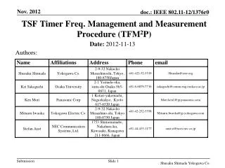
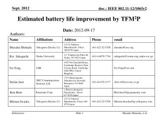
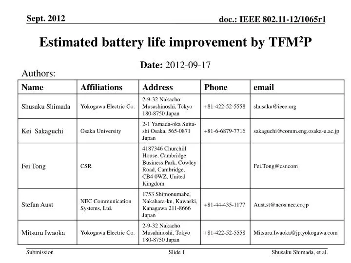
Estimated battery life improvement by TFM2P Authors: • Date:2012-09-17 Shusaku Shimada, et al.
Abstract • Estimated battery life improvement by reduced wake-up timing margin using TFM2P (Time-Freq.Measurement Mechanism & Procedure) is shown. • For sensor scenarios with long communication interval, an accurate wake-up timing control using TSF of which frequency is compensated by TFM2P, may deserve. Shusaku Shimada, et al.
Previous submission & Sensor usage scenario • AP may provide its TSF timer accuracy information (11-12/130r0 by Seunghee Han, et. al., already in SFD). • Previous submission (11-12/872r1) introduced TFM2P, which is imperative to minimize unnecessary wake-up time margin. • Use case 1 (sensors and meters) suggests various type of battery operated scenarios, where 11ah is going to provide quick communication with very long sleep/hibernating periods. Shusaku Shimada, et al.
Principle tactics of battery life improvement • Wake-up (TSF) time of sensors to synchronize with AP • Schedule for sensor nodes to wake-up • Sleep as long as possible while data can be stored in sensors • Awake as short as possible by communicating quickly • Accuracy of TSF frequency measurement sets the duty ratio including wake-up margin which can be minimized by using TFM2P. • ; for small • c.f. Wake-up timing margin △= 40ppm, (20ppm X’tals at each peer) Shusaku Shimada, et al.
Reduction of wake-up timing margin • Wake-up Scheduling and required timing margin; • △=±20@AP ±20@STA=±40ppm; • Wasting battery power , PW(average) ∝ △ ; for deployed sensors PW(worst case) ∝ 2△ ; for possible worst case • (2) TFM2P may improve above wake-up margin, approx. 1/10 reduction. scheduled wake-up time (Communication interval) TSF master (AP) wake-up timing margin △ due to timer freq. accuracy TSF slave (STA) actual sleep duration sleep again wake-up Shusaku Shimada, et al.
Accurate wake-up by TFM2P • Compensated TSF timer reduces required wake-up margin; • △compensated = 3.5ppm, which is required for residual tolerance. • (2) For instance, △compensated = ±1.5ppm@AP ± 2ppm@STA; Temperature stability of TSF timer and residual tolerance of TFM2P scheduled wake-up time (Communication interval) TSF master (AP) less wake-up margin using compensated TSF timer only for residual tolerance TSF slave (STA) actual sleep duration sleep again Wake-up Shusaku Shimada, et al.
Estimated battery life improvement w/t TFM2P An example using Li Coin Cell* [ Use case 1a,1c,1d,1e/f ] Portable sensor which dumps queued data a few times a day Battery Life (year) Comm. interval (hour) Battery condition: Cell capacity ~90mAh, Self discharge ~1% of full capacity/year Tx Power : 20mW Tx Data size: 463 octet @ 150kbit/s and 1500 octet @ 3Mbit/s Data rate : 150kbit/s (MCS0 rep2) and3Mbit/s (MCS9) TSF Timer Oscillator supply current : 1usec (continuous) *note : e.g. Panasonic Li coin cell CR2016 Shusaku Shimada, et al.
Estimated battery life improvement w/t TFM2P An example using AAAA ZnMnO2 Cell** [ Use case 1a,1c,1d,1h ] Fixed sensor deployed in wide area or indoor which send out set of data hourly Battery Life (year) Comm. interval (hour) Battery condition: Cell capacity ~300mAh, Self discharge ~4% of full capacity/year Tx Power : 250mW Tx Data size:@ 250 octet Data rate : 150kbit/s (MCS0 rep2) and3Mbit/s (MCS9) TSF Timer Oscillator supply current : 1usec (continuous) **note : AAAA ZnMnO2 Cell, of which capacity is depending on discharge current Shusaku Shimada, et al.
Estimated battery life improvement w/t TFM2P An example using Li Button Cell*** [ Use case 1c,1d,1e/f,1h ] Temporal sensor which send out a raw or stored data several times an hour Battery Life (day) Comm. interval (hour) Battery condition: Cell capacity ~35mAh, Self discharge ~1% of full capacity/year Tx Power : 1mW Tx Data size:@ 16 octet Data rate : 150kbit/s (MCS0 rep2) and3Mbit/s (MCS9) TSF Timer Oscillator supply current : 1usec (continuous) ***note : e.g. Panasonic Li button Cell BR1220 Shusaku Shimada, et al.
Frequency Measurement Mechanism • dot11MgmtOptionFrequencyMsmtActivated (New) Properly apart two time measurements may result substantially different results as shown. Sending STA(f1) Receiving STA(f2) PHY assisted time-stamp may help. t1=ToD(M1) M1 t2=ToA(M1) Ack t3=ToD(M1) t4=ToA(Ack) M1 t1and t4 are known offset1=[(t2-t1)-(t4-t3)]/2 Ack f1= 1/k(t5-t1) f2= 1/k(t6-t2) t5=ToD(M2) M2 t6=ToA(M1) t8=ToA(Ack) Ack t7=ToD(M1) M2 t5and t8 are known offset2=[(t6-t5)-(t8-t7)]/2 Ack Shusaku Shimada, et al.
Prerequisite for Procedure: An stability example of tuning fork crystal ºC (Degree Centigrade ) Information exchange (before performing FM2 ) - Stability (My side) and/or - Achievable minimum tolerance (your side) Frequency Deviation (ppm) X’tal frequency accuracy : ±20ppm Sensor node (TSF Slave) : 3.5ppm @ 25±10 ºC -0.035 ppm / (change in ºC)2 max parabolic curve AP (TSF Master): Temperature stabilized timer may be used 1.5ppm for -10 ~ 60 ºC Shusaku Shimada, et al.
Open issue: Procedure (1) • AP may advertise possible worst accuracy before TFM2P • Worst TSF accuracy (11-12/0130r0; already in SFD) • In addition, AP may advertise best tolerance by TFM2P • Achievable minimum tolerance and/or TSF timer stability (to be used for TFM2P interval calculation) as well. • STA may inform its own residual tolerance to AP after compensation performed, if requested. • Either STA or AP select appropriate TFM2P scheme; • Initiates explicit TFM2P handshake with specific interval between two time measurements by STA if needed. • perform implicit TFM2P at every wake-up time as well. Shusaku Shimada, et al.
Open issue: Procedure (2) • AP may collect information below; • STA’s TSF frequency tolerance • STA’s TSF timer stability • AP may broadcast information below to all STAs; • TSF frequency tolerance of worst STA • TSF timer stability of worst STA Shusaku Shimada, et al.
Straw Poll (1) • Do you agree that the enhanced power saving mechanism of 11ah should provide any frequency measurement procedure of TSF timer to improve the battery life? • Yes • No • Abstain Shusaku Shimada, et al.
Straw Poll (2) • Do you agree to explore more on TFM2P (Time-Freq.Measurement Mechanism & Procedure) in slide 10 to be included finally in SFD of 11ah? • Yes • No • Abstain Shusaku Shimada, et al.
References • [1] 11-12/130r0 “beacon reception of long sleeper” • [2] IEEE802.11 -2012 Wireless LAN Medium Access Control (MAC) and Physical Layer (PHY) Specifications • [3] 11-12/0872r1 “time frequency measurement mechanism and procedure” Shusaku Shimada, et al.