Download

1 / 15
210 likes | 736 Views
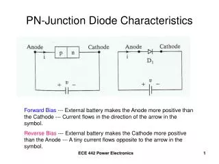
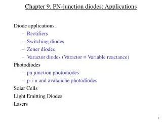
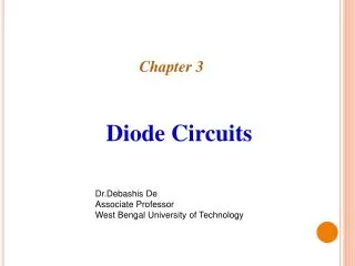
Chapter 6-1. PN-junction diode: I-V characteristics. Topics : PN Junction under bias (qualitative discussion) Ideal diode equation Deviations from the ideal diode Charge-control approach. PN junction under various bias conditions. V A = 0. V A < 0. V A > 0. E. E. E. p. n. p n.

E N D
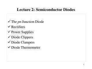
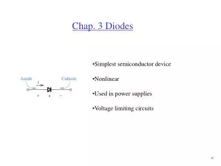
Chapter 6-1. PN-junction diode: I-V characteristics • Topics: • PN Junction under bias (qualitative discussion) • Ideal diode equation • Deviations from the ideal diode • Charge-control approach
PN junction under various bias conditions VA = 0 VA < 0 VA > 0 E E E p n p n Hole diffusion current Hole diffusion current Hole diffusion current Hole drift current Hole drift current Hole drift current Electron diffusion current Electron diffusion current Electron diffusion current Electron drift current Electron drift current Electron drift current
Effect of bias on diffusion current • When the diode forward-bias-voltage is increased, the barrier for electron and hole diffusion current decreases linearly. See the band diagram. • Since the carrier concentration decreases exponentially with energy in both bands, diffusion current increases exponentially as the barrier is reduced. • As the reverse-bias-voltage is increased, the diffusion current decreases rapidly to zero, since the fall-off in current is exponential.
Effect of bias on drift current • When the reverse-bias-voltage is increased, the net electric field increases, but drift current does not change. In this case, drift current is limited NOT by HOW FAST carriers are swept across the depletion layer, but rather HOW OFTEN. • The number of carriers drifting across the depletion layer is small because the number of minority carriers that diffuse towards the edge of the depletion layer is small. To a first approximation, the drift current does not change with the applied voltage.
Effect of bias on the “net” current • |Idrift| does not change with applied voltage, VA • |Idiff| varies exponentially with applied voltage (Why?) |Idiff| = I0 exp (VA/Vref) where I0 and Vref are constants. • Net current = Idiff – Idrift • At equilibrium, VA = 0; Net current = 0 • | Idiff |VA = 0 = | Idrift |VA = 0 = I0 • At any applied voltage, VA, • since Idrift= I0 at any voltage.
Quantitative solution • Assumptions which must hold • The diode is being operated under steady state conditions • A non-degenerately doped step junction models the doping profile • The diode is one-dimensional • Low-level injection (conditions) prevail in the quasi-neutral regions • There are no processes other than drift, diffusion, and thermal recombination-generation taking place inside the diode, GL=0
Hole diffusion current Hole drift current Electron diffusion current Electron drift current Majority and minority carrier concentration under equilibrium p-side n-side pp0 nn0 E pn0 np0 -xpxn Subscript “0” refers to equilibrium conditions
Relationship between carrier concentration and Vbi because Therefore, and Strictly, these concentrations are at the depletion layer edge
Majority and minority carrier concentration under bias When an external voltage is applied, the minority carrier concentration at the edge of the depletion layer will change. If a forward voltage (VA=positive) is applied, the barrier will be lower and carrier injection (diffusion part) will increase.The minority carrier concentration at the edge of the depletion layer will increase. If a reverse voltage (VA = negative) is applied, the barrier for carrier injection (diffusion part) will increase, and the minority carrier concentration at the edge of the depletion layer will decrease. The drift of minority carriers across the junction does not change much with applied voltage. Why? At VA = 0, the carrier injection and the drift of minority carriers cancel each other such that an equilibrium conc. is maintained. If “low-level-injection” condition is assumed, then the majority carrier concentration will not change under any of the above conditions.
Relationship between carrier concentration and VA since (Vbi – VA) is the net voltage (or barrier) when a forwarded voltage is applied. At low-level injection: pp= pp0; Recall that then
Minority carrier concentration profile under bias + VA np(0) pn(0) np= np0 +np(x'') pn = pn0 + pn(x') pn0 np0 x'' x'
Relationship between applied voltage and excess minority carrier concentration