Download
1 / 29
310 likes | 543 Views
Chapter 2 Diode Applications. Objectives. Explain and analyze the operation of both half and full wave rectifiers. Explain and analyze filters and regulators and their characteristics. Explain and analyze the operation of diode limiting and clamping circuits.

E N D
Objectives • Explain and analyze the operation of both half and full wave rectifiers • Explain and analyze filters and regulators and their characteristics • Explain and analyze the operation of diode limiting and clamping circuits • Explain and analyze the operation of diode voltage multipliers • Interpret and use a diode data sheet • Troubleshoot simple diode circuits
Introduction The basic function of a DC power supply is to convert an AC voltage to a smooth DC voltage.
Half Wave Rectifier A half wave rectifier(ideal) allows conduction for only 180° or half of a complete cycle. The output frequency is the same as the input. The average VDC or VAVG = Vp/
Half Wave Rectifier Peak inverse voltage is the maximum voltage across the diode when it is in reverse bias. The diode must be capable of withstanding this amount of voltage.
Transformer-Coupled Input Transformers are often used for voltage change and isolation. The turns ratio of the primary to secondary determines the output versus the input. The fact that there is no direct connection between the primary and secondary windings prevents shock hazards in the secondary circuit.
Full-Wave Rectifier A full-wave rectifier allows current to flow during both the positive and negative half cycles or the full 360º. Note that the output frequency is twice the input frequency. The average VDC or VAVG = 2Vp/.
Full-Wave RectifierCenter-Tapped This method of rectification employs two diodes connected to a center-tapped transformer. The peak output is only half of the transformer’s peak secondary voltage.
Full-Wave Center Tapped Note the current flow direction during both alternations. Being that it is center tapped, the peak output is about half of the secondary windings total voltage. Each diode is subjected to a PIV of the full secondary winding output minus one diode voltage drop. PIV=2Vp(out) +0.7V
The Full-Wave Bridge Rectifier The full-wave bridge rectifier takes advantage of the full output of the secondary winding. It employs four diodes arranged such that current flows in the same direction through the load during each half of the cycle.
The Full-Wave Bridge Rectifier The PIV for a bridge rectifier is approximately half the PIV for a center-tapped rectifier. PIV=Vp(out) +0.7V Note that in most cases we take the diode drop into account.
Power Supply Filters And Regulators As we have seen, the output of a rectifier is a pulsating DC. With filtration and regulation this pulsating voltage can be smoothed out and kept to a steady value.
Power Supply Filters And Regulators A capacitor-input filter will charge and discharge such that it fills in the “gaps” between each peak. This reduces variations of voltage. The remaining voltage variation is called ripple voltage.
Power Supply Filters And Regulators The advantage of a full-wave rectifier over a half-wave is quite clear. The capacitor can more effectively reduce the ripple when the time between peaks is shorter.
Power Supply Filters And Regulators Being that the capacitor appears as a short during the initial charging, the current through the diodes can momentarily be quite high. To reduce risk of damaging the diodes, a surge current limiting resistor is placed in series with the filter and load.
Power Supply Filters And Regulators Regulation is the last step in eliminating the remaining ripple and maintaining the output voltage to a specific value. Typically this regulation is performed by an integrated circuit regulator. There are many different types used based on the voltage and current requirements.
Power Supply Filters And Regulators How well the regulation is performed by a regulator is measured by it’s regulation percentage. There are two types of regulation, line and load. Line and load regulation percentage is simply a ratio of change in voltage (line) or current (load) stated as a percentage. Line Regulation = (VOUT/VIN)100% Load Regulation = (VNL – VFL)/VFL)100%
Diode Limiters Limiting circuits limit the positive or negative amount of an input voltage to a specific value. This positive limiter will limit the output to VBIAS + .7V
Diode Limiters The desired amount of limitation can be attained by a power supply or voltage divider. The amount clipped can be adjusted with different levels of VBIAS. This positive limiter will limit the output to VBIAS + .7V The voltage divider provides the VBIAS . VBIAS =(R3/R2+R3)VSUPPLY
Diode Clampers A diode clamper adds a DC level to an AC voltage. The capacitor charges to the peak of the supply minus the diode drop. Once charged, the capacitor acts like a battery in series with the input voltage. The AC voltage will “ride” along with the DC voltage. The polarity arrangement of the diode determines whether the DC voltage is negative or positive.
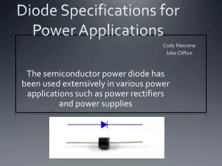
The Diode Data Sheet The data sheet for diodes and other devices gives detailed information about specific characteristics such as the various maximum current and voltage ratings, temperature range, and voltage versus current curves. It is sometimes a very valuable piece of information, even for a technician. There are cases when you might have to select a replacement diode when the type of diode needed may no longer be available.
Troubleshooting Our study of these devices and how they work leads more effective troubleshooting. Efficient troubleshooting requires us to take logical steps in sequence. Knowing how a device, circuit, or system works when operating properly must be known before any attempts are made to troubleshoot. The symptoms shown by a defective device often point directly to the point of failure. There are many different methods for troubleshooting. We will discuss a few.
Troubleshooting Here are some helpful troubleshooting techniques: • Power Check: Sometimes the obvious eludes the most proficient troubleshooters. Check for fuses blown, power cords plugged in, and correct battery placement. • Sensory Check: What you see or smell may lead you directly to the failure or to a symptom of a failure. • Component Replacement: Educated guesswork in replacing components is sometimes effective.
Troubleshooting Signal tracing is the most popular and most accurate. We look at signals or voltages through a complete circuit or system to identify the point of failure. This method requires more thorough knowledge of the circuit and what things should look like at the different points throughout.
Troubleshooting This is just one example of troubleshooting that illustrates the effect of an open diode in this half-wave rectifier circuit. Imagine what the effect would be if the diode were shorted.
Troubleshooting This gives us an idea of what would be seen in the case of an open diode in a full-wave rectifier. Note the ripple frequency is now half of what it was normally. Imagine the effects of a shorted diode.
Summary • The basic function of a power supply to give us a smooth ripple free DC voltage from an AC voltage. • Half-wave rectifiers only utilize half of the cycle to produce a DC voltage. • Transformer Coupling allows voltage manipulation through its windings ratio. • Full-Wave rectifiers efficiently make use of the whole cycle. This makes it easier to filter. • The full-wave bridge rectifier allows use of the full secondary winding output whereas the center-tapped full wave uses only half.
Summary • Filtering and Regulating the output of a rectifier helps keep the DC voltage smooth and accurate. • Limiters are used to set the output peak(s) to a given value. • Clampers are used to add a DC voltage to an AC voltage. • Voltage Multipliers allow a doubling, tripling, or quadrupling of rectified DC voltage for low current applications.
Summary • The Data Sheet gives us useful information and characteristics of device for use in replacement or designing circuits. • Troubleshooting requires use of common sense along with proper troubleshooting techniques to effectively determine the point of failure in a defective circuit or system.