Download
1 / 19
190 likes | 321 Views
The CBM Time-of Flight wall. Ingo Deppner for the CBM-TOF Group Physikalische Institut Uni. Heidelberg. Outline: Motivation CBM-ToF Requirements Conceptional Design Pad MRPCs Wide strip MRPCs Summary. Motivation. CBM Physics topics Deconfinement / phase transition at high ρ B

E N D
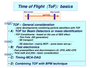
The CBM Time-of Flight wall Ingo Deppner for the CBM-TOF Group Physikalische Institut Uni. Heidelberg • Outline: • Motivation • CBM-ToF Requirements • Conceptional Design • Pad MRPCs • Wide strip MRPCs • Summary Ingo Deppner
Motivation • CBM Physics topics • Deconfinement / phase transition at high ρB • QCD critical endpoint • The equation-of-state at high ρB • chiral symmetry restoration at high ρB Observables • excitation function and flow of strangeness and charm • collective flow of hadrons • particle production at threshold energies • excitation function of event-by-event fluctuations • excitation function of low-mass lepton pairs • in-medium modifications of hadrons (ρ,ω,φ → e+e-(µ+µ-), D) In order to measure all these observables with an high accuracy, we need a good particle identification Ingo Deppner
Motivation Particle ID • Hadrons: STS + TRD + TOF • Electrons: STS + MVD + TRD +TOF +ECAL • Muons: STS + MUCH + TOF • Open Charm: STS + MVD • Hyperons: STS • Photons: ECAL Kaon acceptance depends critically on TOF resolution Ingo Deppner
CBM-ToF Requirements • full system time resolution sT ~ 80 ps • Efficiency > 95 % • Rate capability < 20 kHz/cm2 • Acceptable cross-talk and charge-sharing. • Low power electronics (~75.000 channels). • Pile-up < 5% • Occupancy < 5 % (for Au-Au(central) at E=25 GeV/A) • Sufficient space resolution Timing RPCs are one of the possibilities to fulfill the CBM-ToF requirements Ingo Deppner
CBM-ToF Requirements Timing RPC with: • active area: A = 120 m2 • counter time resolution: sT ~ 50 ps • rate capability: R ~ 0.5 – 20 kHz/cm2 • granularity: DA ~ 6 – 100 cm2 • operation mode: free running Which is the best solution to adjust the granularity – pad or strip? Ingo Deppner
Maximal pad size? depends on required timing resolution fora quadratic pad: Dxmax = sT· v · 12Dxmax = 3,5 cm sT : timing resolution (sT ~ 50ps)v : signal velocity (v = 20 cm/ns) pad Dx a a = Dxmax/ 2 = 2,5 cm Conceptional Design In order to accommodate the different granularities as a function of the polar angle, four different regions were defined: • Pad/narrow strip region: 2.5 x 2,5 cm2 (rate: 20 - 8 kHz/cm2 , area: 12 m2 , #SM: 8) • Strip/narrow strip region: 25 x 1 cm2 (rate: 8 - 3.5 kHz/cm2 , area: 24 m2 , #SM: 16) • Strip region: 50 x 1 cm2 (rate: 3.5 – 1.5 kHz/cm2, area: 36 m2 , #SM: 24) • Strip region: 50 x 1 cm2 (rate: 1.5 – 0.5 kHz/cm2 , area: 48 m2 , #SM: 32) main tasks that have to be solved are rate capability and granularity Ingo Deppner
Conceptional Design 1 SM with 120 pad RPC active area is not overlaped active area: 5 x 25 cm2 read out: single ended channels: 120 x 20 = 2400 / SM glass: low resistive / ceramics 1 SM with 20 strip RPC active area slightly overlaped active area: 32 x 25 cm2 read out: both sides channels: 20 x 32 x 2 = 1280 / SM glass: low resistive 1 SM with 10 strip RPC active area slightly overlaped active area: 32 x 50 cm2 read out: both sides channels: 10 x 32 x 2 = 640 / SM glass: low resistive 1 SM with 10 strip RPC active area slightly overlaped active area: 32 x 50 cm2 read out: both sides channels: 10 x 32 x 2 = 640 / SM glass: float (+ warming up) In total ~ 75000 channels Ingo Deppner
CBM-TOF Groups Ingo Deppner
13 cm Pad MRPC Glass type: common / silicateHV electrode: colloidal graphiteNumber of gaps: 10Gap width: 0.25mmGlass thickness: 0.7mmGas mixture: Freon/iso-butane/SF6 92%/3%/5% Pad MRPC developed at Tsinghua university, China First preliminary results Pad structure of the pickup electrode Pad:2 cm x 2 cm Ingo Deppner Talk by Jingbo Wang
Ceramic MRPC efficiency Ceramic MRPC developed at Forschungszentrum Dresden Rossendorf 300 kHz/cm2 Number of gaps: 4Gap width: 0.3 mmCeramic thickness: 2 mmGas mixture: Freon/iso-butane/SF6 85%/10%/5% time resolution Talk by Lothar Naumann Ingo Deppner
Ultrathin glass Pad RPC Pad „mini“-RPC developed at Institute for High Energy Physics, Protvino Ammosov , V. Gapienko, A. Semak, Yu. Sviridov, V. Zaets, E. Usenko Ingo Deppner
narrow strip MRPC Narrow strip MRPC developed at NIPNE, Bucharest cluster size time resolution BUCT1 – 9.5 kV efficiency Talk by Mariana Petris Ingo Deppner
Wide Strip RPC Wide strip MRPC with common and low resistive glass developed at Tsinghua university, China e ~95 %sT~70-80 ps e ~95 %sT~70-80 ps Talk by Diego Gonzalez-Diaz Ingo Deppner Talk by Jingbo Wang
Wide Strip RPC Strip MRPC developed at UST China Glass type: float HV electrode: Licron spray (40 MW/cm2)Number of gaps: 10Gap width: 0.25 mmGlass thickness: 0.7 mmGas mixture: Freon/iso-butane/SF6 92%/3%/5% Cross talk at neighbar strip: ~ 3% Ingo Deppner
Wide Strip RPC reflectometer measurements Fully differential Strip MRPC developed at Physikalische Institut Uni. Heidelberg Imp. ~ 80W active area: 28 x 16.5 cm strips: 16 strip / gap: 7 / 3 mm glass thickness: 0.55 mm float number of gaps: 8 gap width: 220 mm gas: Reclin/SF6/iso-But 85/10/5 pickup electrode Counter is designed for an impedance of 100Wstrip size ~ avalanche size (FOPI) total efficiency ~ 95% Ingo Deppner
f [kHz/cm2] Theory and simulation Diego Gonzalez-Diaz, GSI USTC counter from DC-model A,B: constantq: charger: glass resistivityd: glass thicknessf: flux HD counter probability of pure cross-talk: 1-3% Ingo Deppner
Summary rate capability of float glass can be improcved by warming up (~factor 10/26K) Time line • Demonstrators end 2009 • Electronics chain end 2009 • Demonstrators with ‘final’ electronics end 2010 • TDR end 2011 • Full size prototypes end 2012 • Construction 2012-2014 • Integration 2014-2015 Ingo Deppner
thank you for your attention Contributing institutions: Tsinghua Beijing, NIPNE Bucharest, LIP Coimbra, GSI Darmstadt, USTC Hefei, PI Heidelberg, KIP Heidelberg, INR Moscow, ITEP Moscow, IHEP Protvino, FZD Rossendorf, KU Seoul, RBI Zagreb. Ingo Deppner
Wide Strip RPC HV electrode surface resistance 100 M/cm2 Imp. ~ 80W trigger area licron layer glass substrate Cu-strip reflectometer measurements pickup electrode Ingo Deppner