Download
1 / 51
510 likes | 626 Views
requirements and layout of the CBM ToF wall. Diego González-Díaz (GSI-Darmstadt) A. Berezutskiy (SPSPU-Saint Petersburg), G. Kornakov (USC-Santiago de Compostela), M. Ciobanu (GSI-Darmstadt), J. Wang (Tsinghua U.-Beijing). Some references used in this talk.

E N D
requirements and layout of the CBM ToF wall Diego González-Díaz (GSI-Darmstadt) A. Berezutskiy (SPSPU-Saint Petersburg), G. Kornakov (USC-Santiago de Compostela), M. Ciobanu (GSI-Darmstadt), J. Wang (Tsinghua U.-Beijing)
Some references used in this talk [1a] H. Alvarez Pol et al., 'A large area timing RPC prototype for ion collisions in the HADES spectrometer', NIM A, 535(2004)277. [2a] A. Akindinov et al., 'RPC with low-resistive phosphate glass electrodes as a candidate for CBM TOF', NIM A, 572(2007)676. [3a] J. Wang et al., paper in preparation. [4a] L. Lopes et al., 'Ceramic high-rate RPCs', Nuclear Physics B (Proc. Suppl.), 158(2006)66. [5a] D. Gonzalez-Diaz et al., 'The effect of temperature on the rate capability of glass timing RPCs', NIM A, 555(2005)72. [6a] A. Ammosov et al., talk at XIII CBM collaboration meeting, Darmstadt, Germany. [7a] L. Nauman et al., talk at XIV CBM collaboration meeting, Split, Croatia. [1] A. Mangiarotti et al., 'On the deterministic and stochastic solution of Space-Charge models and their impact in high resolution timing' talk at RPC Workshop Seoul, 2005. [2] G. Chiodini et al., 'Characterization with a Nitrogen laser of a small size RPC', NIM A 572(2007)173. [3] A. Colucci et al., 'Measurement of drift velocity and amplification coefficient in C2H2F4-isobutane mixtures for avalanche-operated resistive-plate counters', NIM A, 425(1999)84. [4] W. Riegler et al., 'Detector physics and simulations of resistive plate chambers', 500(2003)144 . [5] E. Basurto et al., 'Time-resolved measurement of electron swarm coefficients in tetrafluoretane (R134a)', Proc. to 28th ICPIG, Prague, 2007. [6] P. Fonte, V. Peskov, 'High resolution TOF with RPCs', NIM A, 477(2002)17. [7] P. Fonte et al., 'High-resolution RPCs for large TOF systems', NIM A, 449(2000)295. [8] A. Akindinov et al. 'Latest results on the performance of the multigap resistive plate chamber used for the ALICE TOF', NIM A 533(2004)74. [9] G. Aielli et al., 'Performance of a large-size RPC equipped with the final front-end electronics at X5-GIF irradiation facility', NIM A 456(2000)77. [10] S. An et al., 'A 20 ps timing device—A Multigap Resistive Plate Chamber with 24 gas gaps', NIM A 594(2008)39. [11] A. Blanco et al., 'In-beam measurements of the HADES-TOF RPC wall', NIM A 602(2009)691. [12] W. Riegler, D. Burgarth, 'Signal propagation, termination, crosstalk and losses in resistive plate chambers', NIM A 481(2002)130. [13] T. Heubrandtner et al., NIM A 489(2002)439.
Talk layout • CBM at FAIR-Darmstadt. • RPC working principle. • Rate capability of various prototypes. • Avalanche simulation. • Induction simulation. • Cross-talk and FEE simulation. • Comparison with data.
The CBM physics goal at SIS-100 L.V. Bravina et al., Phys. Rev. C60 (1999) 044905 E. Bratkovskaya, W. Cassing Au+Au collisions up to 11 AGeV: exploring properties of dense hadronic (resonance) matter in the vicinity of the phase transition This T-μB phase-space region has been measured before (AGS, SPS). Idea: take advantage of the new technologies and focus on rare observables (open charm, di-leptons, hyper-nuclei, multi-strange hyperons, J/Ψ, Ψ')
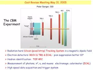
The Compressed Baryonic Matter Experiment Transition Radiation Detectors Tracking Detector Electro- magnetic Calorimeter Muon detection System Ring Imaging Cherenkov Detector Silicon Tracking Stations Projectile Spectator Detector (Calorimeter) Vertex Detector Dipole magnet Resistive Plate Chambers (TOF)
The CBM-TOF wall. Design requirements • Overall time resolution (including start time) σT = 80 ps. • Occupancy < 5 % for Au-Au central collisions at E=25 GeV/A. • Space resolution ≤ 5 mm x 5 mm. • Efficiency > 95 %. • Pile-up < 5%. • Rate capability = 20 kHz/cm2. • Multi-hit capability (low cross-talk). • Compact and low consuming electronics (~65.000 electronic channels). • Multi-strip design in the outer region, due to the very low occupancies. Why? -> Why not?. If electrically possible it is mechanically much more easy.
RPC geometry in simulation (I) In order to accommodate the different granularities as a function of the polar angle, five different regions were defined: • Padregion (1): 2.0 x 2.0 cm2 ( 27072 channels, ~10 m2) • Strip region (2): 2.0 x 12.5 cm2 ( 3840 x 2 channels, ~10 m2) • Strip region (3): 2.0 x 25.0 cm2 ( 5568 x 2 channels, ~30 m2) • Strip region (4): 2.0 x 50.0 cm2 ( 6150 x 2 channels, ~60 m2 ) • Strip region (5): 2.0 x 100.0 cm2 ( 2900 x 2 channels, ~60 m2 ) TOTAL ( ~65000 channels, ~170m2)
A multi-gap RPC in general. Here a differential RPC ('a la' STAR), just for the sake of 'electrical elegance' *parameters not from STAR differential pre-amplifier particle HV insulator with Vbreak>10-15 kV standard PCB with read-out strips on one side Rin +V at least 4 gas gaps (~0.3 mm thick) -V float glass HV coating with R~100 MΩ/□
More electrical schemes are (un)fortunately possible HADES-SIS FOPI-SIS ALICE-LHC -V -V V V -V -V STAR-RHIC -V -V V V ! V -V V -V V S. An et al., NIM A 594(2008)39 [10] all these schemes are equivalent regarding the underlying avalanche dynamics... but the RPC is also a strip-line, and this is manifested after the avalanche current has been induced. And all these strip-lines have a completely different electrical behavior. HV filtering scheme is omitted
How (we believe) is the avalanche produced? g/ve~ 1 ns g/vi~1 μs ith τg~1 s(glass relaxation time) prompt (e-) component Slow (ion) component avalanche growth decreases! space-charge limitation Eav~E E=ΔV/g e--I+ particle see [4], for instance
A parentheses: rate capability of various CBM prototypes for small fluxes and in a simple DC-model see for instance: D. Gonzalez-Diaz et al. Nucl. Phys. B (Proc. Suppl.) 158(2006)111
A parentheses: rate capability and DC-model systematics In first order, it fits!
Back to the avalanche. How to create a simple avalanche model 8.7 Raether limit log10 nelectrons space-charge regime ~7.5 ~7 exponential-growth regime threshold ~2 exponential-fluctuation regime 0 to tmeas t avalanche Furry-type fluctuations simplifying assumptions • The stochastic solution of the avalanche equation is given by a simple Furry law(non-equilibrium effects are not included). • Avalanche evolution under strong space-charge regime is characterized by no effective multiplication. The growth stops when the avalanche reaches a certain number of carriers called here ne,sat. • The amplifier is assumed to be slow enough to be sensitive to the signal charge and not to its amplitude. We work, for convenience, with a threshold in charge units Qth.
Parameters of the gas used for input: α* (effective Townsend coefficient), vd (drift velocity), no (ionization density) little dependence with mixture! no [mm-1] HEED (from Lippmann[4]) αextrapolated to mixture by using Freon's partial pressure: αmixture = αFreon(E/fFreon) fFreon *purely phenomenological! continuous line: data from Basurto et al. in pure Freon [5] vddirectly taken from Freon (inspired on microscopic codes) vd,mixture = vd,Freon
Induction and weighting field Ez read-out ws-s ~0 mm g=0.3 mm t=2.5 mm HV w=22 mm wide-pad limit t << w additionally when g<<t (typical situation) Ez does not depend on the position –z- along the gap We use formulas from: problem: under-estimation of Ez for large inter-strip separations T. Heubrandtner et al. NIM A 489(2002)439
MC results. Efficiency and resolution for 'wide-pad' type detectors
MC results. Prompt charge distributions for 'wide-pad' type detectors 1-gap 0.3 mm RPC standard mixture 4-gap 0.3 mm RPC standard mixture Eff = 74% Eff = 60% Eff = 38% simulated simulated measured qinduced, prompt [pC] qinduced, prompt [pC] measured assuming space-charge saturation at ne,sat= 4.0 107 (for E=100 kV/cm) data from Fonte, [6,7] qinduced, total [pC]
First of all... what is a strip? In standard language:- strip: something read-out in two ends/something 'quite rectangular'- pad: something read-out in one end/something 'quite squared' In this talk: A strip is a read-out structure that must be described (due to the phenomena under study) like a transmission-line. In the simplest single-strip description, it is something characterized by 2 magnitudes: a transmission coefficient and a propagation velocity.This is a definition based on the electrical properties of the structure.
Induction + transmission + FEE. Sketch (I) transmission 1 2 induction 4 3 multi-strip FEE response
Induction + transmission + FEE. Sketch (II) • Five stages in order to get a predictive result • Avalanche generation with the previous code. • [->Comparison with eff vs V and fine-tune, if needed, of threshold value. This approach seems to be flexible enough.] • Induction, based on analytical formulas from [13], extrapolated to multiple-gaps by using the effective series permittivity of the corresponding group of layers. • Propagation based on HF simulator APLAC (http://web.awrcorp.com/Usa/Products/APLAC/). • [-> Validation of APLAC for the structure of interest with a pulse generator (nowadays we do not need this step anymore)] • Termination and other circuit elements are included, together with FEE, simulated also with APLAC.
A 2-strip RPC as a loss-less transmission-line. Example (I) W. Riegler, D. Burgarth, NIMA 481(2002)130 [12] see if a 4-gap RPC seen as a transmission-line dominated by skin-effect: small for typical dimensions and rise-times very small, due to the presence of gas and glass two different modes in the transmission line!. This causes 'modal dispersion' unless: true for homogeneous transmission lines! 1) for typical materials (glass) loss-less line! 2)
A 2-strip RPC as a loss-less transmission-line. Example (II) zo = position along the strip where the signal is induced for exponential signals small dispersion high-frequency /large distance / dispersive limit low-frequency /small distance / non-dispersive limit in general very large dispersion the 2 modes are fully decoupled see also [12]
A 2-strip RPC as a loss-less transmission-line. Example (III) 2-strip geometry and signal taken from [12] non-dispersive limit (zo=0) dispersive limit (zo->∞) injected signal cross-talk signal ->Continuous line is the exact analytical solution from [12]. ->Dashed and dotted lines are the numerical solution from APLAC used later in this work.
Cross-talk in an un-terminated line 50 50 anode 1 cathode 1 50 50 50 50 anode 2 cathode 2 50 50 signal from BC420 scintillator (used as current generator) 50 50 anode 3 cathode 3 50 50 50 anode 4 cathode 4 50 50 50 anode 5 cathode 5 50 50
Cross-talk in a terminated line 50 50 anode 1 cathode 1 50 50 50 50 anode 2 cathode 2 50 50 50 50 anode 3 cathode 3 50 50 50 50 anode 4 cathode 4 50 50 50 50 anode 5 cathode 5 50 50
Cross-talk and signal shape low dispersion counter, typical working conditions, BW=260 MHz cross-talk constant, very independent from the signal shape Take as a typical shape the one of an avalanche produced at the cathode Even for dispersive counters it is reasonable since most of the charge is coming from that region
Typical plots where to look at • Transverse profile of the efficiency, with and w/o valid charge. • Cross-talk probability. Integral and as a function of the charge in the main strip. • Resolution when a second hit is present in the module. • Cluster sizes (not shown here). • Dependence with HV of the above observables (not shown here).
Zc~13 Ω 1.6 m long wide-strip (P. Fonte et al., 2002) Cm=88 pF/m BW=1.5 GHz Rin=50 Ω experimental conditions: Π, E=3.5 GeV, low rates, trigger width = 2 cm Cg=514 pF/m Cm/Cg =17% Fct=50%! very dispersive! transverse scan 'fine-tunning' Fct=40% good agreement with MC avalanche 80%-90% measured cross-talk levels reproduced
Zc~18 Ω 35-cm long wide-strip, mirrored and shielded Cm experimental conditions: ~mips from p-Pb reactions at 3.1 GeV, low rates, trigger width = 2 cm (< strip width) BW=260 MHz Rin=100 Ω ... ... Cg little dispersive Fct=11% transverse scan 'fine-tunning' inter-strip region dominated by trigger width Fct=19% probability of pure cross-talk: 1-3% Analysis with high resolution tracking on-going.
Zdet~20 Ω 50-cm long wide-strip, mirrored and not shielded Cm=18 pF/m BW=260 MHz Rin=100 Ω experimental conditions: ~mips from p-Pb reactions at 3.1 GeV, low rates, trigger width = 2 cm (< strip width) ... ... Cg=276 pF/m Cm/Cg =6.5% Fct=11.5% dispersive similar cross-talk levels than in previous case probability of pure cross-talk: 1-3%
Zdiff=80 Ω 30-cm long narrow strip, differential Cm=20 pF/m experimental conditions: ~mips from p-Pb reactions at 3.1 GeV, low rates, high resolution (~0.1 mm) tracking transverse scan ... ... Cdiff=23 pF/m Fct=9% dispersive intrinsic strip profile is accessible! probability of pure cross-talk: 1-3%
1-mlong counter, 12-gap, mirrored and shielded experimental conditions: ~mips from p-Pb reactions at 3.1 GeV, low rates, trigger width = 2 cm (< strip width) long run. Very high statistics. ... ...
The last point: cross-talk influence in the timing of a coincident (double) hit. A simple derivation. space-charge log[q(t)] qth exponential regime t variations in base-line due to cross-talk variations in time at threshold due to cross-talk
Cross-talk influence in timing (simple derivation) Assumptions: • Within the same primary collision cross-talk extends up-to infinite time. • It does not depend on position. • Fluctuations in time of cross-talk signal are smaller than fluctuations coming from the avalanche charge distribution. • Pick-up strips are separated by a typical distance bigger than the area of influence of the avalanche. Charge sharing during induction can be neglected!. • Cross-talk is small, given by Fct. cross-talk is expected to affect timing when
1-m long counter, 12-gap, mirrored and shielded double-hit in any of 3rd neighbors double-hit in any of 2nd neighbors double-hit in any of 1st neighbors no double hit
Multi-strip design at 1-m scale with acceptable cross-talk, small cluster size and small deterioration of time resolution seems doable. Further optimized structures based on simulations are on the way (Fct~1%). Rate capability seems to be achievable. Stability tests already started. -> Detailed optimization based on physics performance soon to follow. Then we will know if cross-talk is 'high' or not. -> Comparisons between simulations and data will continue conclusions and outlook
The FOPI counter Multi-strip-MRPC (MMRPC) Glass: ε=7.5, strip width = 1.64 mm, strip gap = 0.9 mm, strip length = 900 mm copper (20 μm) 8 gaps 1.1 mm 0.22 mm 0.5 mm 1.1 mm
The FOPI counter (11th strip) cathode 50 50 anode 0 50 50 anode 1 50 50 .......... 50 50 anode 11 50 50 anode 12 50 50 anode 13 50 50 anode 14 50 50 anode 15
The FOPI counter (9th strip) cathode 50 50 anode 0 50 50 anode 1 50 50 .......... 50 50 anode 9 50 50 anode 10 50 50 anode 11 50 50 anode 12 50 50 ..........