Download
1 / 42
470 likes | 765 Views
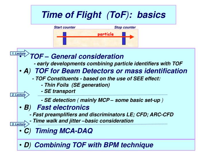
Time of Flight ( ToF ) : basics. Start counter. Stop counter. TOF – General consideration - early developments combining particle identifiers with TOF A ) TOF for Beam Detectors or mass identification - TOF Constituents - based on the use of SEE effect:

E N D
Time of Flight (ToF): basics Start counter Stop counter • TOF – General consideration • - early developments combining particle identifiers with TOF • A) TOF for Beam Detectors or mass identification • - TOF Constituents - based on the use of SEE effect: • - Thin Foils (SE generation) • - SE transport • - SE detection ( mainly MCP – some basic set-up ) • B) Fast electronics • - Fast preamplifiers and discriminators LE; CFD; ARC-CFD • - Time walk and jitter –basic consideration • C) Timing MCA-DAQ 1. Lecture 2. Lecture 3. Lecture • D)Combining TOF with BPM technique
Timing MCA • Classical approach TPHC (TAC) – ADC • TDC • - direct Time-Digitizer (TDC) • - Time - Expansion (Time-to-Charge) • - direct Digital Interpolation TDC • c) DAQ for Timing
Principle of TPHC (TAC) Performance Time resolution ----- FWHM ~ 5ps Differential DNL ----- <+/- 2% Integral INL --------- < 0.1% Ranges ---- 50; 100; 200 ns Multiplier x 1; 10; 100, 1k or 10k Delay ----- 0.5 µs to 10.5 µs Width ----- 1µs to 3 µs Strobe circuitry: INT or EXT mode ADC (13-14 bit) (Dead Time 1-4 µs)
Selection of ADC - DAQ for TAC solution TAC + Standard ADC +CC TAC + DGF (Rev.F) + CC • Linear slope - CC Gen. • VREF comparator • clock • synchronized counter To set the DGF-4C in integrator mode ·set Integrator (ch.#) =1) ·chose an integration time ~ 2-3µs · set gap time of energy filter = 0 To set the Analog Input attenuators: JPx01 - OFFfor 1:7.5 attenuator JPx02 – ON for 50 ohm termination Tconv. = T clock x N SAR-ADC Tconv. ~ 1µs
Principle of Direct Time Digitizer tm(stop) –tm(start) = N. T0(oscillator) even with a clock with F0 ~1-5 GHz the timing resolution is to poor, namely 1ns or 200 ps in comparison with the 5 ps of previous the TAC – ADC combination up-graded versions of TDC: - time expansion; - interpolated; - time vernier
(t” – t’) vs.(tm(stop) –tm(start)) expansion factor
An interpolating Time-to-Digital converter implemented on an FPGA structure Start Stop
A cyclic vernier TDC • - tentative 1ps time resolution • Start_ Slow Digitally Controlled Oscillator -- Slow DCO ~ Ts (period) • coarse counter • Stop Fast DCO ~ Tf(period) • T input= T Sp - TSt= • = Tcoarse + Tfine= NsTs +Nf (Ts-Tf) ~ 65 ns CMOS technology ~ 1ps resolution Y. Park et al, A Cyclic Vernier TDC Converter synthesized from a 65 nm CMOS technology, ISCA2010
Part 3 AMS – Combining TOF technique with Beam Profile Monitors (BPM)
Beam Profile Monitor (BPM) • - Why they are needed ? • to reconstruct the kinematics of the ions after they are decelerated • to energies of ~ 5 MeV/u (in the context of the HISPEC/DESPEC, • also of importance to the RISING/PRESPEC) • slowing down relativistic beams energy straggling • and particle space divergence • Beam Detectors are requested to: - to determine the Beam Profile , - to determine the Particle Trajectories Tracking - combining TOF with BPM ∆M/M ~ 1/300 • and all these at highest transparency and larger active surface!
The total yield of Secondary Electrons emitted when ions pass through a • thin carbon foil function of beam current and tilt angle of the target • Sternglass theory and latter the Modified-Sternglass theory, namely a • two steps mechanism: • - formation of internal secondary electrons in material as a result of • excitation and ionization processes • - SEE (secondary electron emission) - escape from the target Target ┴ θ ( the beam current is interpreted as a temperature effect, i.e. the rise of temperature increased vibrations of the atoms mean free path of electrons is shortened yield decreases) Total SEE yield as a function of the target temperature for Ar+ ions at different energies Total SEE yield as a function of the target’s tilt angle 1) E.J. Sternglass, Phys. Rev. 90 (1953),p.380 and 2) H.P. Garnir et al, SEE from thin foils… NIM 202 (1982), p.182-192
The total yield of Secondary Electrons emitted when ions pass through a thin carbon foil as a function of tilt angle of the target Total SEE yield as a function of the target’s tilt angle γc Target ┴ θ Beam axis at least in the energy range 0.2 – 2 MeV A According to Sternglass, in a tilted target there is an increase of length of the ion track within the “escape zone” which enhance the production of electrons near the surface without modifying the escape probability !! Parameter A shows that at low velocity, 60% of the SEE yield is independent of the angle of incidence and for helium beam, this percentage decreases with the ion energy Cl+ He+ Ion velocity (mm/ns) H.P. Garnir et al, SEE from thin foils…, NIM 202 (1982) p.182-192 and E.J. Sternglass, Phys. Rev. 90 (1953),p.380 and E.J. Sternglass, Phys. Rev. 108 (1957),p.1
Commercial foils (films): • A) Goodfellow • Polycarbonate (PC) (brand names: Lexan; Macrofol; Macrolon) • Density ρ ~ 1.2 g cm-3 • ( minimum) Thickness 2 µm + Al( ρ ~ 2.7 g cm-3) ( Au: ρ ~ 19.3 g cm-3 ) • Polyethylene terephthalate (Polyester, PET, PETP) • (brand names: Amite; Dacron; Hostaphan; Mylar; Melaynar; Terylene etc.) • Densityρ ~ 1.4 (1.3) g cm-3 • (minimum) Thickness 2 µm + Al( ρ ~ 2.7 g cm-3) ( Au: ρ ~ 19.3 g cm-3 ) • Polyimide (brand names: Kapton, Kinel; Upilex; Upimol; Kaprex) • Densityρ ~ 1.42 (1.3) g cm-3 • (minimum) Thickness 25 µm + Al(why only larger as 25µm ??) • B) Jeonyoung Electrochemicals (Gyeonggi-do, South Korea) • is specialized in ultra-thin metal foil surface finishing by Ni, Ag, Cu • - single-sided or double-sided 0. 1~2um-thick Ni-plated copper • Dali Electronics ?( India)(www.domadia.com) • - 1 µm SS 302, SS 304,…SS 318L etc. Ultra thin Stainless Steel Foils • D) …
Secondary electrons path ion path 1cm Cu-Be 20µm diam. @ 1mm 98% transparence see Michael Pfeiffer SIMION simulations W. Starezecki at al./ LNL-Padova NIM 193 (1982) 499-505
Experimental set-up to determine the time spread of an electrostatic mirror. The electrons emitted from both side of the C foil are accelerated by a harp and directed to the MCPs by bending through: - a mirror (a), or - directly (b) ~280 ps (a) • C-foil • 10-20 µg/cm2 • + ~3.5 µg/cm2 • LiF evaporated • onto the C-foil to enhance the • SE emission ~157 ps (b) Time of flight spectrum of: ~6 MeV α particle; both start & stop from MCP detectors - 213 MeV 58Ni elastically scattered at 4 ° from a 20 μg/cm(*2) 12C foil-target W. Starezecki at al./ LNL-Padova NIM 193 (1982) 499-505
Heavy Ion Magnetic Spectrometer @ PRISMA (LNL-Padova ) Lab. test alpha- particles ~ 350 ps beam test 40Ca • Large MCP - 80x100 mm (as @IKP-FAIR) • C-foil ~20µg/cm*2 • Grids at 4mm and only 300eV (see Shapira et al.) • (20µm gold-plated Tungsten@ 1mm) • SE drift path ~ 10 cm • External Magnetic field ~120 Gauss • (important for position resolution!) ~ 400 ps G. Montagnoli et al. NIM A 547 (2005) 455-463
Carbon foil ~ 20 µg/cm2 –self supporting ! • good mass resolution ( 1/300) • ions direction with an uncertainty • smaller than 0.5° and off-line tracking • yields and velocity determination • ext. magnetic field (‘cyclotron’ frequency) • Notes for the file: • - only one HV-PS IKP experience … • - three grids ( 20µm Tungsten + Au @ 1mm) • - magnetic field – reaction chamber size or • external coil ? G. Montagnoli et al. NIM A 547 (2005) 455-463
Gold plated tungsten ~150 µm diameter and • NO Cu round frame and NO rectangular • grounding Cu plates ( shielding, reduce • reflections due to mismatched of • characteristic impedance • two differential amplifier at each end of a • delay line with collection in only one of • the wire of the parallel pair • due to differential amplifier, the signal is • compensated for capacitive coupling, • i.e. only collected charge signal O.H. Oldland, et al, A fats position sensitive MCP for charged particles, NIM A 378 (1996), p.149
- outer collecting winding ~ 700 V • inner collecting winding ~705 V • no-collecting windings ~ 650 V • central electrode ~ 500 V • The characteristic impedance of both delay lines is • Z0 ~ 130 Ω the preamplifier impedance ~ 130 Ω • The differential preamplifier with Zi ~ 300 Ωand • balance-to-balanced transformers with turns ratio • 2.75:1:75 M.B. Williams, S.E. Sobottka- High Resolution Two Dimensional readout of MCP with Large Area Delay Lines, IEEE Trans. NS, 36, Feb.1989, p.227
(position sensitive read-out) 45 mm ( 2x to balance the electrostatic forces) 45 mm Foils: C ~ 30µg/cm2 Mylar ~ 290 µg/cm2 3-4 mm Foil at 30° (relative to the beam direction ) 3-4 mm 3-4 mm D. Shapira et al. / Factors affecting the performance of SED, thin foil…BPM, NIM A 449 (2000) 396-407
Effect of multiple scattering • The number of secondary electrons: • two tendencies: - proportional with Zp2/Ep (atomic number and particle energy) • Code SRIM to estimate multiple • scattering contribution of thicker • foils 16O ions exiting the foil • binned as a function of polar angle • 2µm Mylar • (580 µg/cm2) • tilted at 30° SRIM formula: Angular spread in particle trajectories after traversing 4 µm thick Mylar D. Shapira et al. / Factors affecting the performance of SED, thin foil…BPM, NIM A 449 (2000) 396-407 K.E. Pferdekämpfer, H.G. Clerc, Energy spectra of SE eject by ions from foils, Z. Physik A 280 (1977), p.155 R.A. Baragiola, Heavy particle induced SE from solids, NIM B 78 (1993) p.223
Ion Beam Diagnostics with Particle Detectors The use of a thin CsI(Tl) scintillator combined with gamma detectors to identify the radioisotopes as a fingerprint of the emitting nucleus Paolo Finocchiaro, Low Intensity Ion Beam Diagnostics with Particle Detectors, INFN-LNS
GANIL- fast sensitive MCP based charge particle tracking The foil structure: ~0.5 µm Mylar + 20 µg/cm2 Al + 500Å CsI (SE x5) ~50-100 µg/cm2 O.H. Oldland, et al, A fast position sensitive MCP for charged particles, NIM A 378 (1996), p.149
External magnetic field - helical trajectory with a so called ”cyclotron” frequency F = qE + qv x B v=v┴ + v║ Circular trajectory in a plane perpendicular to the E and B - fields with the ‘cyclotron’ frequency : ω=(qB)/(γm) Radius of the orbital motion: R =(mv)/(qB) The measured detector resolution ‘ρ’ plotted together with the theoretical curve – both function of the magnetic field for different target voltages: 3; 5 and 7 kV resp. 3kV 5 kV 7 kV [tesla] [tesla] [tesla] O.H. Oldland, et al, A fats position sensitive MCP for charged particles, NIM A 378 (1996), p.149
TOF-BPM at ELBE electron accelerator • intrinsic timing resolution 240 ps (FWHM) • position resolution 1.8 +/-0.3mm (FWHM) • foil thickness 163 µg/cm2 • intend to be used at SIS-GSI, Darmstadt • relative large MCP detectors ( with active area > 12 cm2 ) K.Kosev et al, A high-resolution TOF-Tracking capabilities…, NIM A 594 (2008) p.178
Apparent (intrinsic) MCP detectors resolution ~ 170 ps d ~ 270 mm Foil 1-to-Foil 2 Simulation – SIMEON 3D ( http://www.simion.com ) Detection efficiency forward emitted SE 40Cl ~ 40 MeV • from foil to mirror front side (field free drift) region • inside electrostatic mirror (~ homogeneous field ??) • electrostatic mirror out and MCP in (-out ?) Alpha-particle ~ 5.8MeV K. Kosev et al, FZ Dresden-Rosendorf NIM A 594 (2008) 178-183
Calculated position resolution as a function of the grid wires pitch. ----------- for particle deflected in the middle of the electrostatic mirror __________ for particle deflected at the edge of the electrostatic mirror
Angular resolution after reflection - • ~ 1.5 - 2.5.10 ² sr • TOF time resolution - ~300 ps • Transparency/module - ~70 % - G. Pascovici,Institute of Nuclear Physics, Univ. of Cologne
Michael Pfeiffer SIMION3D simulation for TOF, BPM for the HISPEC-DESPEC @ FAIR
The hexanode readout • Expanding the application • of delay-line anodes for • experiments with serious • multihit demands • Maximize the multihit • minimize the electronic • dead-time • With three layer arrangement • one can build also a delay- • line anode with central-hole, • e.g. to allow the beam pass • through Sketch of the “Hexanode” X;Y;Z – 2D O. Jagutzki et al, Multiple Hit Readout of a MCp with a three layer DL anode, IEEE Trans. NS, Vol. 49,(2002), p. 2477
Single Delay Line (SDL) configuration which • consist of a planar zig-zag electrode etched into • a copper layer on a substrate, that runs the entire length of the anode pattern. • It is interleaved with two sets of wedge shaped electrodes that are half a period out of phase the determination of the X and Y event centroid coordinates are totally independent for the SDL anode configuration. • The charge is divided between the delay • line and the wedges in a ratio that may • be chosen to suit the X and Y resolution • requirements. • Material: SiO2; Duroid ε ~10 & HF; 5mm thick; Cu~18µ R0~ 43 Ω; v/2 ~ 0.53 mm/ns Td ~ 60 ns size: 53 x 53 mm Xc= (T +Td) .v/2 v-signal propagation T- the difference in signal arrival times Yc= fQ1/(Q1+Q2) Q1;Q2thecharge signal detected at the two wedge electrodes Qi - CSP O.Siegmund et al, High resolution Delay Line readouts for MCPs, NIM A310 (1991)p311
T- Output Timing Pulser In tr < 600ps (intrinsic) T1 • Timing Preamplifier • - Ultra Fast current • tr (intrinsic) ~ 600ps • Position Preamplifiers • Differential read-out • (X2(active)- X1(passive)) X1 (X1-X2) X2 DDL differential read-out
DAQ G. Pascovici,Institute of Nuclear Physics, Univ. of Cologne