Download
1 / 48
530 likes | 983 Views
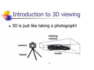
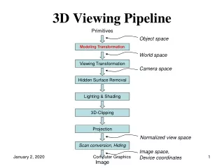
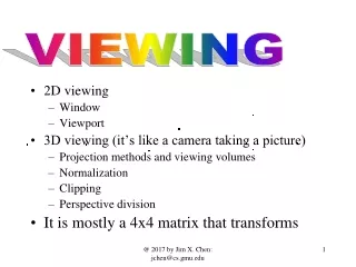
3D Viewing. 3D Viewing Transformation Pipeline. MC. Modeling Transformation. WC. Viewing Transformation. VC. Projection Transformation. PC. Normalization Transformation and Clipping. NC. Viewport Transformation. DC. 3D Viewing Transformation Pipeline. MC. Modeling Transformation.

E N D
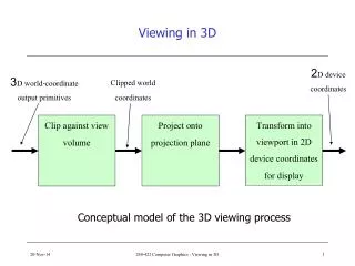
3D Viewing Transformation Pipeline MC Modeling Transformation WC Viewing Transformation VC Projection Transformation PC Normalization Transformation and Clipping NC Viewport Transformation DC
3D Viewing Transformation Pipeline MC Modeling Transformation WC Viewing Transformation VC Projection Transformation PC Normalization Transformation and Clipping NC Viewport Transformation DC
yw yv xv V zv P0 xw zw 3D Viewing V view up vector P0 = (x0, y0, z0) view point N viewplane normal Viewplane is at point zvp in negative zv direction V is perpendicular to N N
yv xv zv 3D Viewing xv yv zv is a right-handed viewing coordinate system v u n
yw yw xw xw zw zw 3D Viewing Transformation from World to Viewing Coordinates: 1. Translate viewing coordinate origin to the origin of world coordinate system 2. Apply rotations to align xv yv zv axes with xw yw zw axes respectively MWC,VC = R . T yv xv zv P0 yv xv zv
3D Viewing Transformation Pipeline MC Modeling Transformation WC Viewing Transformation VC Projection Transformation PC Normalization Transformation and Clipping NC Viewport Transformation DC
Projections isometric axonometric orthogonal Parallel cavalier oblique cabinet Perspective
Projections view plane view plane Perspective projection Parallel projection
Orthogonal Projection Axonometric: displays more than one face of an object Isometric: projection plane intersects each coordinate axis at the sane distance from the origin Isometric
3D Viewing Transformation Pipeline MC Modeling Transformation WC Viewing Transformation VC Projection Transformation PC Normalization Transformation and Clipping NC Viewport Transformation DC
yv xv zv Orthogonal Projection Clipping view volume clipping window far plane near plane
Orthogonal Projection Normalization Mortho,norm . R . T ynorm znorm (1,1,1) xnorm yv (-1,-1,-1) xv zv
Oblique Projection Oblique projection: projection path is not perpendicular to the view plane view plane
Oblique Projection yv (xp,yp,zvp) xv zv a f (x,y,zvp) (x,y,z)
Oblique Projection xp = x + L1 (zvp – z) cos f yp = y + L1 (zvp – z) sin f shearing transformation L1 f view plane
Oblique Projection Cavalier Projection Cabinet Projection f = 450 f = 300 f = 450 f = 300
yv xv zv Oblique Projection (xp,yp,zvp) window a f Vp view volume (x,y,zvp) Vp (x,y,z)
Oblique Projection MWC,VC . Morth,norm . Mobl Mobl,norm window window shear Vp Vp orthogonal coordinates
Parallel Projection View plane Viewer’s position
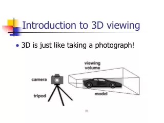
Perspective Projection View plane Viewer’s position
Perspective Projection yv projection reference point (prp) xv zv view plane
Perspective Projection yv (xp,yp,zvp) (xprp,yprp,zprp) zv xv (x,y,z)
Perspective Projection At any point (xp, yp, zp) along the projection line: zp = zvp xp = x (zprp-zvp) / (zprp-z) + xprp (zvp-z) / (zprp-z) yp = y (zprp-zvp) / (zprp-z) + yprp (zvp-z) / (zprp-z)
Perspective Projection Vanishing point y x z One-point perspective projection x-axis vanishing point z-axis vanishing point Two-point perspective projection
Perspective Projection Far plane Near plane Viewer’s position
Perspective Projection Far plane Near plane Viewer’s position
Perspective Projection Clipping window Rectangular Frustum view volume projection reference point (prp) q Far clipping plane Near clipping plane
Perspective Projection P=(x, y, z, 1) Ph=(xh, yh, zh, h) xp = x (zprp-zvp) / (zprp-z) + xprp (zvp-z) / (zprp-z) yp = y (zprp-zvp) / (zprp-z) + yprp (zvp-z) / (zprp-z) h = zprp-z xh = x (zprp-zvp) + xprp (zvp-z) yp = y (zprp-zvp) + yprp (zvp-z) xp = xh /h yp = yh /h
Perspective Projection Ph= Mpers . P Mpers = zprp-zvp 0 -xprp xprpzprp 0 zprp-zvp -yprp yprpzprp 0 0 sz tz 0 0 -1 zprp
Perspective Projection Symmetric Frustum Frustum center line Far plane view volume Clipping window Near plane q view plane (xprp, yprp, zvp) (xprp, yprp, zprp)
Perspective Projection 200 600
Perspective Projection Then apply normalization transformation Parallelepiped view volume Symmetric Frustum Perspective Mapping
Perspective Projection 1. Transform to asymmetric frustum (z-axis shear) 2. Normalize viewvolume Parallelepiped view volume Oblique Frustum Perspective Mapping (xprp, yprp, zprp)=(0,0,0)
Perspective Projection shzx= -(xwmin+xwmax)/2.znear Mshear = shzy= -(ywmin+ywmax)/2.znear assuming that viewplane is at the position of the near plane Mpers = Moblpers= Mpers . Mshear 1 0 shzx 0 0 1 shzy 0 0 0 1 0 0 0 0 1 znear 0 0 0 0 -znear 0 0 0 0 sz tz 0 0 -1 0
xv PRP zv Perspective Projection Normalization ynorm (xwmax, ywmaz, zfar) transformed frustum znorm (1,1,1) xnorm yv (-1,-1,-1) (xwmin, ywmin, znear)
Perspective Projection Mnormpers = Mxyscale . Moblpers = = -znearsx 0 sx(xwmin+xwmax)/2 0 0 -znearsy sy(ywmin+ywmax)/20 0 0 sz tz 0 0 -1 0 -2znearsx/(xwmax-xwmin) 0 (xwmin+xwmax)/(xwmax-xwmin) 0 0 -2znearsy/(ywmax-ywmin) (ywmin+ywmax)/(ywmax-ywmin)0 0 0 (znear+zfar)/(znear-zfar) -2.znear.zfar/(znear-zfar) 0 0 -1 0
Perspective Projection For symmetric frustum with field-of-view angle q: Mnormsymmpers = Mnormsymmpers . R . T cot(q/2)/aspect 0 0 0 0 cot(q/2) 00 0 0 (znear+zfar)/(znear-zfar) -2.znear.zfar/(znear-zfar) 0 0 -1 0
3D Viewing Transformation Pipeline MC Modeling Transformation WC Viewing Transformation VC Projection Transformation PC Normalization Transformation and Clipping NC Viewport Transformation DC
Viewport Transformation Mnormviewvol,3Dscreen = ynorm (xvmax, yvmax, 0) znorm viewport screen (1,1,1) xnorm (-1,-1,-1) (xvmin, yvmin, 0) (xvmax-xvmin)/2 0 0 (xvmin+xvmax)/2 0 (yvmax-yvmin)/2 0 (yvmin+yvmax)/2 0 0 1/2 1/2 0 0 0 1
3D Clipping Inside if: -h≤xh≤h, -h≤yh≤h, -h≤zh≤h Use sign bits of h±xh, h±yh, h±zh to set bit1-bit6 6 5 4 3 2 1 far near top bottom right left ynorm znorm (1,1,1) xnorm (-1,-1,-1)
Point Clipping Test sign bits of h±xh, h±yh, h±zh If region code is 000000 then inside otherwise eliminate
Line Clipping 1. Test region codes • if 000000 for both endpoints => inside • if RC1 V RC2 = 000000 => trivially accept • if RC1Λ RC2 ≠ 000000 => trivially reject 2. If a line fails the above tests, use line equation to determine whether there is an intersection
Polygon Clipping 1. Check coordinate limits of the object • if all limits are inside all boundaries => save the entire object • if all limits are outside any one of the boundaries => eliminate the entire object 2. Otherwise process the vertices of the polygons • Apply 2D polygon clipping Clip edges to obtain new vertex list. • Update polygon tables to add new surfaces If the object consists of triangle polygons, use Sutherland-Hodgman algorithm.
OpenGL • glMatrixMode (GL_MODELVIEW) • gluLookAt (x0, y0, z0, xref, yref, zref, Vx, Vy, Vz) Designates the origin of the viewing reference frame as, • the world coordinate position P0=(x0, y0, z0) • the reference position Pref=(xref, yref, zref) and • the viewup vector V=(Vx, Vy, Vz) • glMatrixMode (GL_PROJECTION) • gluOrtho (xwmin, xwmax, ywmin, ywmax, dnear, dfar) Orthogonal projection
OpenGL • glMatrixMode (GL_PROJECTION) • gluPerspective (theta, aspect, dnear, dfar) • theta: field-of-view angle (00 – 1800) • aspect: aspect ratio of the clipping window (width/height) • dnear, dfar: positions of the near and far planes (must have positive values) • glFrustum (xwmin, xwmax, ywmin, ywmax, dnear, dfar) • if xwmin = -xwmax and ywmin = -ywmax then symmetric view volume • glViewport (xvmin, yvmin, vpWidth, vpHeight) • xvmin, yvmin: screen position of the lower-left corner of the viewport relative to the lower-left corner of the display window • vpWidth, vpHeight: width and height of the viewport
OpenGL float eye_x, eye_y, eye_z; void init (void) { glClearColor (1.0, 1.0, 1.0, 0.0); // Set display-window color to white. glMatrixMode (GL_PROJECTION); // Set projection parameters. glLoadIdentity(); gluPerspective(80.0, 1.0, 50.0, 500.0); // degree, aspect, near, far glMatrixMode (GL_MODELVIEW); eye_x = eye_y = eye_z = 60; gluLookAt(eye_x, eye_y, eye_z, 0,0,0, 0,1,0); // eye, look-at, view-up } void main (int argc, char** argv) { glutInit (&argc, argv); // Initialize GLUT. glutInitDisplayMode (GLUT_SINGLE | GLUT_RGB); // Set display mode. glutInitWindowPosition (50, 500); // Set top-left display-window position. glutInitWindowSize (400, 300); // Set display-window width and height. glutCreateWindow ("An Example OpenGL Program"); // Create display window. glViewport (0, 0, 400, 300); init ( ); // Execute initialization procedure. glutDisplayFunc (my_objects); // Send graphics to display window. glutReshapeFunc(reshape); glutKeyboardFunc(keybrd); glutMainLoop ( ); // Display everything and wait. }