Download
1 / 25
260 likes | 440 Views
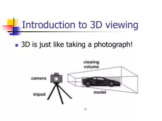
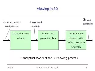
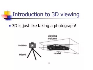
3D Viewing. CS 288 10/5/98 Vic. One point perspective projection of cube cutting Z axis. Parallel Orthographic Projections. View Plane.

E N D
3D Viewing CS 288 10/5/98 Vic
View Plane • Projection Plane, or view plane, is defined by a point on the plane called the view reference point (VRP) and a normal to the plane called the view plane normal (VPN). • The view plane may be anywhere with respect to the world objects to be projected : in front, cut through, or behind the objects.
Defining a window • Given a view plane, a window on the view plane is needed. • The contents are mapped into the viewport and any part of the 3D world that projects outside of the window is not displayed.
Defining a window • To define a window on the view plane you need to specify the minimum and maximum window coordinate. • We must also define two orthogonal axes in the view plane along which we can measure these coordinates.
Defining a window • The orthogonal axes that define the window comprise what is called the viewing reference coordinate (VRC) system. • The origin of the VRC is the view reference point (VRP). • The two axes that define the VRC are the view plane normal (VPN) and the view-up vector (VUP).
VRC System • The View Plane Normal (VPN) is the n-axis and is normal to the viewing plane. • The view-up vector (VUP) determines the v-axis direction on the view plane. • The axes u, v, n form a right handed coordinate system.
Projection Reference Point (PRP) • The Center of Projection (COP) and the Direction of Projection (DOP) are defined by a Projection Reference Point (PRP). • If the projection type is PERSPECTIVE, the PRP is the Center of Projection. • If the projection type is PARALLEL, the DOP is from the PRP to the CW.
View Volumes • The view volume bounds that portion of the world that is to be clipped out and projected onto the view plane. • For perspective projections, the view volume is a semi-infinite pyramid with apex at the PRP and edges passing through the corners of the window.
View Volumes • Positions behind the COP are not included in the view volume and are not projected. • Our eyes see an irregularly shaped cone like view volume • For mathematical reasons, the view volume is considered to be pyramidal and is consistent with the concept of a rectangular viewport.
View Volumes • For parallel projections the view volume is an infinite parallelepiped with sides parallel to the Direction of Projection (DOP) which is the direction from the PRP to the CW.
Clipping Planes • In order to limit the number of output primitives projected to the view plane, we want the view volume to be finite. • We specify the bounds of the view volume with a front clipping plane (hither) and a back clipping plane (yon).
Clipping Planes • The clipping planes are parallel to the view plane and their normal is the VPN. • The planes are specified by the front distance (F) and the back distance (B).
Normalized Projection Coordinates (NPC) • Imagine a unit cube extending from 0 to 1 for each of the 3 dimensions. • xmin to xmax • ymin to ymax • zmin to zmax
Normalized Projection Coordinates (NPC) • The front clipping plane is the zmax plane • The back clipping plane is zmin plane • The z=1 face of the unit cube is mapped to the largest square that can be inscribed on the display.
Examples of 3D Viewing • Thursday