Download
1 / 58
590 likes | 918 Views
Prof. Lei He Electrical Engineering Department, UCLA LHE@ee.ucla.edu http://eda.ee.ucla.edu. Package-Chip Co-Design. Outline. Overview of Chip Package Co-design IO planning and placement Power integrity in package Reading: package tutorial at ee201c wiki. Wire-bond vs Flip-chip.

E N D
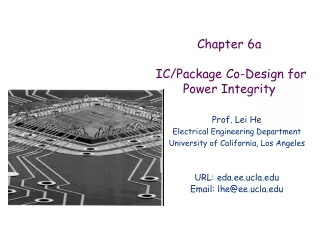
Prof. Lei He Electrical Engineering Department, UCLA LHE@ee.ucla.edu http://eda.ee.ucla.edu Package-Chip Co-Design Lei HE, UCLA
Outline • Overview of Chip Package Co-design • IO planning and placement • Power integrity in package • Reading: package tutorial at ee201c wiki Lei HE, UCLA
Wire-bond vs Flip-chip • Wire bonding • Cheap Implementation • Difficult to design • IO signals are at boundary • High inductance (~1nH) • More worry on core and IO power distribution during design and analysis Lei HE, UCLA
Wire-bond vs Flip-chip • Flip-chip • IO cells can be over entire of chip area • Low inductance (~0.1nH) • High pin count, high cost • Less worry on power delivery Lei HE, UCLA
Silicon Package Board (Cadence) Lei HE, UCLA
Connection from die to board • Die (IO cells -> RTL routing -> bumps) • -> package (bumps -> escape routing -> package routing -> balls) • -> board Lei HE, UCLA
IC Physical Design Package Physical Design I/O Locations IBIS Models Package Modeling/Simulation IC Modeling/Simulation VLSI-Centric Design (Problematic) • IC and package tools very separated: (From P. Franzon) Lei HE, UCLA
On-Chip Design Concerns • Physical Concerns • Die Netlist Connectivity (logic cells to IO cells) • System Connectivity (IO cells to package) • Power Network (power planes to power IO cells to logic cells) • Electrical Concerns • Core Timing Constraints • System Timing Constraints • Power Budget • Signal Integrity and Reliability Constraints • Supply voltage scaling imposes very tight noise margins on chip and package designs • Significant noise contribution from core switching • But greater on-chip exposure to package-side (i.e., IO) SSN Lei HE, UCLA
Package Design Concerns • Physical Concerns • Reduce stack-up layers and package cost • Place IO cells and decoupling capacitance • Complete escaping and package routing • Electrical Concerns • Reduce SSN noise • Lower impedance of power distribution • Meet timing constraints, especially for bus and differential pairs Lei HE, UCLA
Typical Package Design Cycle Pad/package Iteration: P&R of IO/Pad cells, Pins; Pwr/gnd and inter-cell connections; PCB pin locations (x,y); Package/Pad/IO Rule checking (PRC): SI, timing, clocks, IO voltages, assembly rules, special regions Floorplanning of IO/Pad/Pins; Define Netlist hierarchy/manipulations Manufacturing and NRE Costs; Die, Substrate, Package Verify user specified requirements and rules; PCB pins, Power grid, # VSS/VDD, decoupling caps, EMI, ESD, Vias Defining Interfaces, Signals, PLL, Power, Clock, # pins, # IOs Package/Substrate Architecture Exploration (start ~4/5 months before Tapeout) Finalize IOs/Pads/Pins; Package Tapeout Lei HE, UCLA
Needs of Chip-Package Co-Design • High system frequency • 400 MHz buses becoming common • On-chip exposure to package noise • Simultaneous switching noise • Package resonance • High density packaging and high pin count • Difficult to layout and escape-route • Again, more SSN for on-die circuit • Tight time to market • Convergence of package and IO becomes a bottleneck if chip and package handled by separated flows Lei HE, UCLA
Keys Problems to Solve • Chip and package co-extraction and co-simulation • Difficult to obtain accuracy for sign-off • More difficult to achieve efficiency with accuracy or fidelity for planning and design • Challenging to handle mutual inductance and large number of ports • Co-design focuses on important links between chip and package • Chip side: IO buffer design, noise isolation circuitry, P/G network, IO pad macro-placement, RDL estimation, • Package side: Package stack-up, P/G plane design, macro-placement of balls and pins, and estimation of escape routing • key issues: • IO planning and placement, power delivery system Lei HE, UCLA
Outline • Overview of Chip Package Co-design • IO planning and placement • Design constraints • Multi-stage solutions • Power integrity in package Lei HE, UCLA
Design Constraints for IO Planning and Placement • Power integrity • Timing • I/O standards • Core and board floorplanning Lei HE, UCLA
Power Integrity Constraints • Power domain constraint • I/O cell voltage specification • Cells from same domain prefer physically closer • Minimize power plane cut lines in the package • Provide proper power reference plane for traces • Depend on physical locations of I/O cells • Proper signal-power-ground (SPG) ratio • Primary and secondary P/G driver cells • Minimize voltage drop and Ldi/dt noise Lei HE, UCLA
Timing Constraints • Substrate routes in package varies significantly • Length spans from 1mm to 21mm • Timing varies more than 70ps for SSTL_2 • I/O cells with critical timing constraints shall take this into account • Differential pairs and bus prefer to escape in parallel and in same layer Lei HE, UCLA
I/O Standard Related Constraints • High-speed design high-speed I/O • I/O standard requirements • Relative timing requirements on signals • Likely to be connected to the same interface at other chips, so prefer to keep relative order to ease routing • Closeness constraint • Less process variation • Bump assignment feasibility constraint Lei HE, UCLA
Floorplan Induced Region Constraints • Top-down design flow • PCB floorplan • Bottom-up design • Chip floorplan • I/O cells have region preference • Which side? • What location? Lei HE, UCLA
Connection from die to board • Die (IO cells -> RTL routing -> bumps) • -> package (bumps -> escape routing -> package routing -> balls) • -> board Lei HE, UCLA
Flow of IO planning and placement • Global I/O and Core co-placement • Bump array Placement • I/O site definition • Constraint driven detailed I/O placement Lei HE, UCLA
Global I/O and Core Co-placement • Minimize both wire length and power domain slicing • Power domain plans I/O cells location, and becomes region constraints for I/O cells for the following steps Lei HE, UCLA
Bump and Site Definition • Regular bump pattern is preferred • Escapability analysis • Regular I/O site is preferred • I/O proximity • RDL planar routability analysis • I/O sites more than I/O cells • SPG ratio consideration • Flexibility for later bump assignment • I/O super site: a cluster of I/O sites Lei HE, UCLA
Assign I/O Cells to Super I/O Sites • A set of region constraints (Ri, CiR) • A rectangular restricted area Ri for I/O cells CiR • E.g., floorplan, power domain definition, wire length minimization • A set of clustering constraints (Li, CiL) • The spread of I/O cells should be less than a bound • E.g., I/O standard const., floorplan, timing • A set of differential pair constraints • Different pairs should be connected to bumps with similar characteristics • E.g., timing • Solve by ILP or LP followed by netflow-based legalization • Paper 2C-4, Wednesday afternoon at this conference Lei HE, UCLA
Experiment Setting • Real industrial designs • Constraints not include the ones that are generated internally Lei HE, UCLA
Experiment Result • Obtain 100% CSR (constraint satisfaction ratio) in short runtime Lei HE, UCLA
Power Plane Cuts Core Domain Plane Cut Island IO Domain Lei HE, UCLA
Power Domain Routing Domain Routing Lei HE, UCLA
Outline • Chip Package Co-design Flow • IO planning and placement • Power integrity in package • Overview and modeling • Decap insertion • Impedance based • Noise-based Lei HE, UCLA
Time domain power and signal integrity Signal Noise Analysis coupled with power plane models Superposition of Power Noise on Signal Noise IBIS, SPICE and PEEC models are employed Power Integrity • Frequency domain analysis of Power Planes Impedance • Return Path Modelling for EMI and SSN analysis • EMI Analysis • Package Plane Resonance Lei HE, UCLA
PDS: Power Distribution System Detailed Network Modeling is needed for accurate analysis of Core and IO Power Lei HE, UCLA
Ideal Package Power Planes • Early Package Design Exploration • Planes have no holes or perforations • Perfect Microstrip or Stripline Patterns • Impedance is well conditioned Lei HE, UCLA
Non-ideal Package Power Planes • Detailed Plane Modeling • Planes are split for different voltage domains • Planes could have any number of holes / perforations • Microstrip or Stripline Patterns: imperfect Lei HE, UCLA
PDS Modelling • Wire capacitance can be extraction using 2.5D model [He-et al, DAC’97] • With extension to arbitrary routing angle • Plane capacitance needs to consider impact of wires in between • Inductance is must and can be formula based • Bonding wires have well controlled shapes • Susceptance (L-1) makes sparsification easier • But sign-off often needs 3D field solver Lei HE, UCLA
PDS Design • Assign power planes in package stackup • Assign power domains: V18, V25, Vanalog,… • Decide via stapling • Improve power delivery • Reduce current loop and eliminate noise • Assign P/G balls Lei HE, UCLA
PDS Concerns • DC Concerns • On-Chip IR Drop • Not a big concern in Flip-chip Designs • In-Package IR Drop • Important but still very small • In-PCB IR Drop • Can be ignored • AC Concerns • Low impedance Network across a broad frequency spectrum • Reduce inductive effective to reduce SSN • Control Chip/Package resonance Lei HE, UCLA
Power Plane Noise (AC vs DC) Lei HE, UCLA
PDS Design • PDS Impedance • Smaller Zo larger current • PDS Bandwidth • Maintain Zo from 0 to fmax • Decide on Decap Allocation • High speed drivers draw current from nearby decoupling capacitors • Decoupling capacitors reduce the size of the current loop Lei HE, UCLA
Chip-Package Plane Resonance Resonances are produced due to inductance and capacitance Z Capacitor becomes inductive beyond its self resonant frequency, f(SR) Inductive Capacitive frequency Resonant frequency is Need a set of capacitors to cover small, medium, and high frequency ranges Lei HE, UCLA
Decoupling capacitors optimization • Needs for power integrity • Reduce resonance. • Reduce effective inductance and resistance. • Different levels of decoupling capacitors • Board, package, chip • Different effective frequency range. • Decoupling capacitors is not perfect capacitor • ESL • ESR • Lower ESL and ESR, higher cost • Designing of decoupling capacitors needs to determine • Values • Location • Decoupling capacitor type Lei HE, UCLA
Impact of decoupling capacitors Lei HE, UCLA
Existing Solutions • Manual trial-and-error approaches • [Chen et al., ECTC ’96] • [Yang et al., EPEP 2002] • Automatic optimization • [Kamo et al., EPEP 2000], [Hattori et al., EPEP 2002] • Ignore ESL and ESR. • [Zheng et al., CICC 2003] • Use impedance as noise metric • [Chen et al., ISPD 2006] • Noise driven decap insertion Lei HE, UCLA
Limit of Impedance Metric • Can not capture noise accurately • Will Lead to large over-design Lei HE, UCLA
Incremental impedance computation • When adding one decoupling capacitor Zd at port k • the new impedance from port j to port i is • When removing one decoupling capacitor Zd at port k • the new impedance from port j to port i is Lei HE, UCLA
Time complexity • With one or a few decoupling capacitors inserted • O(np2): np is the number of ports • Existing work: O(np3) • Especially suitable for trial-and-error or iterative methods • Only a few decoupling capacitors changed in each iteration • Able to compute only impedance or I/O ports before updating rest ports Lei HE, UCLA
Noise Calculation • FFT methods • Frequency components of noise from port j to port i • Worst case noise from all ports • Superposition Lei HE, UCLA
Algorithm • Simulated annealing with objective function • pi: Penalty function for noise violation • ci: cost of decoupling capacitor • α, β: weights Lei HE, UCLA
Example • 4 types of decoupling capacitors • 3 I/O ports • Each connected to 10 I/O cells • 90 possible location for decoupling capacitors • Total 93 ports • Worst case noise bound: 0.35V Power planes Lei HE, UCLA
Experiment results: noise based • Cost=20 Lei HE, UCLA
Comparison: Impedance Based • Cost=72 • 3X larger than noise based • Impedance bound is not met but noise bound has already been met. • Overdesign Lei HE, UCLA
Runtime Comparison • 10x speedup compared to method based on admittance matrix inversion Lei HE, UCLA