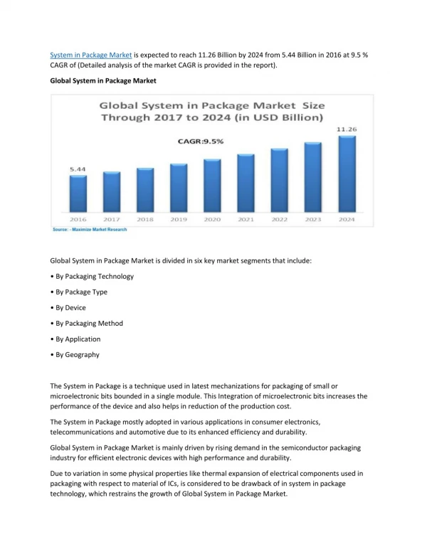
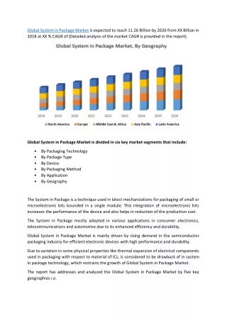
Download
1 / 22
410 likes | 911 Views
System in Package and Chip-Package-Board Co-Design. Progress Report Jia-Wei Fang, Kuan-Hsien Ho, and Yao-Wen Chang. The Electronic Design Automation Laboratory Graduate Institute of Electronics Engineering National Taiwan University August 14, 2008. Outline.

E N D
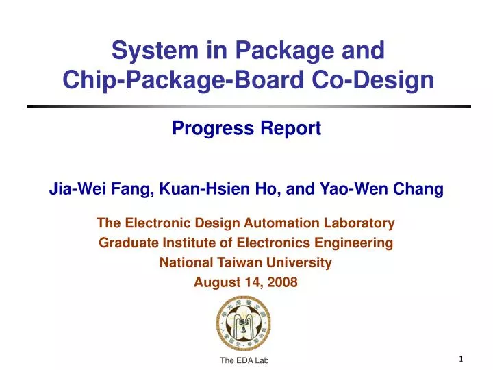
System in Package and Chip-Package-Board Co-Design Progress Report Jia-Wei Fang, Kuan-Hsien Ho, and Yao-Wen Chang The Electronic Design Automation Laboratory Graduate Institute of Electronics Engineering National Taiwan University August 14, 2008
Outline • System in Package • Introduction • Problem Formulation • Extensions • Placement and Routing for Chip-Package-Board Co-Design Considering Differential Pairs • Introduction • Problem Formulation • Placement and Routing Algorithm • Experimental Results • Conclusions • Schedule
System in Package (SiP) • Can get higher deign performance and is easier for implementation than that of Systems on Chip (SoC) • Place multiple dies/flip-chips on the same package • Stack specific dies • Locate fingers around each group of dies • Connect nets among dies, flip-chips, and the package Through silicon via Bonding wire Stacked Dies Finger Pad Metal layers Flip-chip Package wire Die Ball Ball BGA package 3
SiP Problem Formulation • Problem: • Given dies with pads, flip-chips with balls, a PGA/BGA package with pins/balls, a netlist containing pre- and free-assignment nets, and design constraints • Place dies, corresponding fingers of dies, and flip-chips on the PGA/BGA package, then assign signals and route wires among dies, flip-chips, and the package • Objectives: • Maximize routability • Minimize total wirelength under the design constraints
Extensions • Package placement to • Multiple dies placement • Ball arrangement to • Finger arrangement • Signal assignment for fingers and pins to • Signal assignment for pads and pins • Pre-assignment and free-assignment signal routing • Differential-pair routing to • Other routing constraints
Outline System in Package Introduction Problem Formulation Extensions Placement and Routing for Chip-Package-Board Co-Design Considering Differential Pairs Introduction Problem Formulation Placement and Routing Algorithm Experimental Results Conclusions Schedule 6
Chip-Package-Board Co-Design • Advantages: • Give higher flexibility to design a system • Can achieve much higher performance • Our contribution: • present the first placement and routing algorithm for chip-package-board co-design considering differential pairs Finger Bonding wire Package wire Die Top metal layer BGA Pin Bump ball Metal layers PCB wire PCB
Differential Pairs • Differential-Pair (DP) routing is a popular technique for high-speed PCB designs due to its noise immunity, EMI reduction, and ground bounce insensitivity • However, the signal pair should be transmitted in close proximity with similar wirelength to simultaneously absorb the noise
Problem of Chip-Package-Board Co-Design • Problem: • Given a die with fingers, a placement of components with pins, the numbers of BGA and PCB metal layers, and a netlist • Generate and place the package and then assign signals and route wires from component pins to fingers via bump balls, considering differential pairs • Objectives: • Maximize routability • Minimize package size, total wirelength, and the number of vias
Design Flow Die (Fingers), Components (Pins) # Layers, Netlist, Design Rules CPB Placement Bump-Ball Arrangement Package Placement Package and PCB Routing Detailed Routing Global Routing Routing Network Construction Any-Angle Routing No Routed & Minimized? Routing Result Output Yes Layer Assignment
Bump-Ball Arrangement • Determine package size (can get the minimum rectangle size) • # bump balls of (r-1) rings < # fingers < # bump balls of r rings Bump ball ring r-1 ring r Fingers
Package Placement • Apply linear programming (LP) to determine the location of the package Pin 3 4 yboundary q (x1, y1) 1 Package Center c (xc, yc) X=0 (x2, y2) 2 (xp, yp) p r y=0 xboundary
Global Routing (1/2) • Two types of nets • Type 1: from a finger to a bump ball • Type 2: from a finger to a component via a bump ball • Apply LP to do global routing • Multi-sources • Single sink Use s2 to choose only the bump pads for Type 1 s2 b1 b4 Netlist: 1, 2, 3 es1_p1 p1 b na f1 b2 b5 Ball t s1 a f2 p2 Pin f3 c Finger b3 b6 Pre-assigned signals Only given a netlist BGA Chip PCB
Global Routing (2/2) • Two types of nets • Type 1: from a finger to a bump ball • Type 2: from a finger to a component via a bump ball • Apply LP to do global routing • Multi-sources • Single sink s2 b1 b4 Netlist: 1, 2, 3 p1 g f1 b2 b5 t s1 f2 p2 Pin f3 h Finger b3 b6 Only given a netlist BGA Chip PCB
Differential-Pair Routing • The signal pair should be transmitted in close proximity and similar wirelength • Apply LP to route the differential pairs • DP constraints • Σ Σ Ψi_j(ei_g - ej_h) = 0 • Σ ΣΨi_jΨg_h(ei_g - ej_h) = 0 s3 s3 3 3 3 3 4 4 4 4 s4 s4 3 3 3 3 4 4 4 4 Bounding box DP node
Layer Assignment • In global routing, integrate all metal layers into one layer • Model the layer assignment as a flow network to distribute nets into each layer after global routing Can only route 2 wires in one layer 1 1 e1l Layer 1 es1 l elt 1 3 3 s Ball t 3 2 r es2 ert 2 2 e2r Finger Layer 2 BGA Chip Flow network
Detailed Routing (1/2) Min. spacing ring Turn : Pins : Bump balls Acute angle Original routing path • The PCB routing does not allow any routing path with an acute angle • The router should check every turning point to avoid any acute angle • Once an acute corner is detected, the two adjacent net segments can be cut off to generate two obtuse angles
Detailed Routing (2/2) Minimum spacing ring Parallelogram Global Routing Result Detailed Routing Result : DP pins : DP bump balls : Pins : Bump balls
Experimental Settings • C++ programming language • 2.8 GHz AMD Opteron Linux workstation • 8 GB memory • Benchmark – 5 real industry designs
Conclusions • We have developed the first placer and router for chip-package-board design, considering • Package size, • Package placement, • Differential pair routing, • Total wirelength, and • Routability optimization • Experimental results have shown that our placement and routing algorithm is very effective, robust, and flexible
Schedule • Problem of Chip-Package-Board Co-Design • Stage 1 (1/2008 – 4/2008): done • Literature survey • Development of a placement and routing algorithm considering the objectives • Stage 2 (5/2008 – 7/2008): done • Implementation of the placement and routing algorithm • Stage 3 (8/2008 – 9/2008): done • Optimization of the objectives • Stage 4-1 (9/2008 – 11/2008) • GUI generation and integration of all functions • Paper writing and documentation • Stage 4-2 (9/2008 – ) • Extensions for Etron Designs