Download

1 / 22
220 likes | 479 Views
Performance Evaluation of 50 nm In 0.7 Ga 0.3 As HEMTs For Beyond-CMOS Logic Applications. D.-H. Kim and J. A. del Alamo MIT. J.-H. Lee and K.-S. Seo Seoul National University. Sponsors: MARCO-MSD, TND Acknowledgement: MBE Technology. IEDM December 14, 2005. Contents. Introduction

E N D
Performance Evaluationof 50 nm In0.7Ga0.3As HEMTsFor Beyond-CMOS Logic Applications D.-H. Kim and J. A. del Alamo MIT J.-H. Lee and K.-S. Seo Seoul National University Sponsors: MARCO-MSD, TND Acknowledgement: MBE Technology IEDM December 14, 2005
Contents • Introduction • Fabrication of InGaAs HEMTs • Characterization of InGaAs HEMTs • Logic Parameters • Scaling Limit • Benchmarking against Si MOSFETs • Conclusions
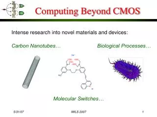
InGaAs HEMTs: beyond-the-roadmap logic technology? Acknowledgement : Robert Chau, Intel
InGaAs HEMTs for the past 20 years Tremendous intrinsic potential of InGaAs HEMT technology Ultra High-speed ICs based on InGaAs HEMT Technology What would it take for InGaAs HEMT to become mainstream logic technology?
Epitaxial Layer Structure • Grown by Molecular Beam Epitaxy • Strain InGaAs Channel & InP Stopper • mn,hall = 11,200 cm2/V-sec
Lg=50 nm Fabrication of 50 nm InGaAs HEMTs PMMA Mesa Copolymer Ohmic ZEP-520 SiNx SiNx EBL & Recess Schottky
EBL for 50 nm T-gate Fabrication - Conventional Method - - Newly Proposed Method - Head Exposure Foot Exposure PMMA ZEP P(MMA-MAA) ZEP Head Exposure PMMA Foot Exposure P(MMA-MAA) Minimum Lg = ~ 100 nm Minimum Lg = 50 nm
Ar-Based RIE InGaAs Ar-Based RIE SiNx InP Etch-stopper Two-Step Recess Technology Selective Wet-Etching ZEP SiNx Two-Step Recess - InGaAs Cap : Wet (Citric Acid) - InP Stopper : Dry (Ar-RIE) < Ref. : Suemitsu et al. (IEDM 1998) >
Optimization : Structure Variation Ti InGaAs InGaAs Ti InP InP tins = 17 nm B = 0.4 eV tins = 11 nm B = 0.6 eV InAlAs InAlAs InGaAs InGaAs Ti/Pt/Au on InP : Type A Ti/Pt/Au on InAlAs : Type B Buried Pt (PtAs4) InGaAs InGaAs Pt InP InP tins = 11 nm B = 0.7 eV tins = 7 nm B = 0.8 eV InAlAs InAlAs InGaAs InGaAs Pt/Ti/Au on InAlAs : Type C Buried Pt on InAlAs : Type D
Output characteristics for InGaAs HEMTs Ti on InP Ti on InAlAs Buried Pt on InAlAs Pt on InAlAs
Subthreshold characteristics for 50 nm InGaAs HEMTs B improvement in subthreshold characteristics tins
1 3 2 3 2 3 1 3 Evaluation Methodology Methodology of Chau (T-Nano 2005) VCC = 0.5 V ION VCC 1 mA/mm ID [mA/mm] VCC IOFF VT VGS - VT at ID = 1 mA/mm & S = 1/Slope(VGS=VT, VDS=VCC) - DIBL = [VT (VDS = VCC) - VT (VDS = 0.05)] / VCC - 0.05 - ION = ID (VGS = VT + VCC, VDS = VCC) - IOFF = ID (VGS = VT − VCC, VDS = VCC)
fT Scaling CPGD (de-embedded) Record fT (Fujitsu) RS & RD (de-embedded) Poor scalability of GM & GO due to short-channel effects Impact of parasitics : RS & RD & CPDG
Contents • Introduction • Fabrication of InGaAs HEMTs • Characterization of InGaAs HEMTs • Logic Parameters • Scaling Limit • Benchmarking against Si MOSFETs • Conclusions
Subthreshold Slope Buried Pt InGaAs HEMTs exhibits S equivalent to Si MOSFETs < Ref. : Chau et al. (T-Nano 2005) >
fT – Power Tradeoff 2.2 13 InGaAs HEMTs show low power & high speed characteristics! < Ref. : Kuhn et al. (VLSI 2004) >
Dependency of Logic Parameters on VT Methodology of Lundstrom (IEDM, 2004) 1 2 VCC VCC 3 3 ION’ ID [mA/mm] IOFF’ VT VT’ VGS Varying VT definition maps tradeoff between ION/IOFF and CV/I Useful to explore suitability of novel devices with non-optimized VT
VT’ – VT < 0 VT’ – VT > 0 GATE DELAY vs. ION/IOFF VT = VT’ @ 1 mA/mm Chau’s approach to gate delay: (CGS + CGD) VCC C V VCC, ION = ION I
GATE DELAY vs. ION/IOFF For 50 nm InGaAs HEMTs, CV/I = 0.66 ps @ VCC = 0.5 V < Ref. : Chau et al. (T-Nano 2005) >
Conclusions • Enhancing B and shrinking tins essential for good logic performance of InGaAs HEMTs • Logic performance of 50 nm InGaAs HEMTs: • ION/IOFF > 104, S < 86 mV/dec, DIBL = 160 mV/V @ VCC = 0.5 V • For ION/IOFF = 104, gate delay < 1 ps @ VCC = 0.5 V • Comparable to state of the art MOSFETs • Future options of InGaAs HEMTs for logic application • E-mode operation, MIS structure & self-aligned scheme