Download
1 / 66
700 likes | 1k Views
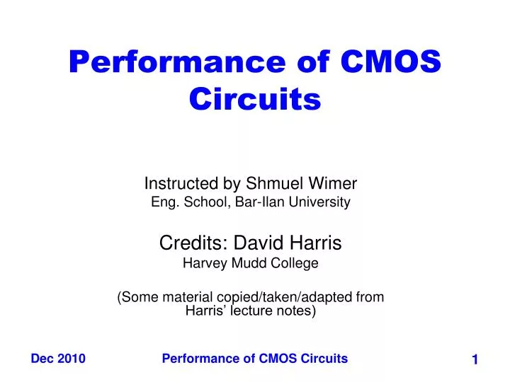
Performance of CMOS Circuits. Instructed by Shmuel Wimer Eng. School, Bar-Ilan University Credits: David Harris Harvey Mudd College (Some material copied/taken/adapted from Harris’ lecture notes). Outline. Gate and Diffusion Capacitance RC Delay Models Power and Energy Dynamic Power

E N D
Performance of CMOS Circuits Instructed by Shmuel Wimer Eng. School, Bar-Ilan University Credits: David Harris Harvey Mudd College (Some material copied/taken/adapted from Harris’ lecture notes) Performance of CMOS Circuits
Outline • Gate and Diffusion Capacitance • RC Delay Models • Power and Energy • Dynamic Power • Static Power • Low Power Design Performance of CMOS Circuits
gate to source gate to drain gate to substrate MOSFET Capacitance Performance of CMOS Circuits
Any two conductors separated by an insulator have capacitance • Gate to channel capacitor is very important • Creates channel charge necessary for operation • Source and drain have capacitance to body • Across reverse-biased diodes • Called diffusion capacitance because it is associated with source/drain diffusion Performance of CMOS Circuits
Gate Capacitance • Approximate channel as connected to source • Cgs = eoxWL/tox = CoxWL = CpermicronW • Cpermicron is typically about 2 fF/mm Performance of CMOS Circuits
Accumulation occurs when Vg is negative (for P material). Holes are induced under the oxide. Cgate = CoxA where Cox = SiO2o/tox Performance of CMOS Circuits
Depletion occurs when Vg is near zero but < Vtn. Here the Cgate is given by CoxA in series with depletion layer capacitance Cdep Performance of CMOS Circuits
Inversion occurs when Vg is positive and > Vtn (for P material). A model for inversion in comprised of Cox A connecting from gate-to-channel and Cdep connecting from channel-to-substrate. Performance of CMOS Circuits
Normalized gate capacitance versus Gate voltage Vgs. • High freq behavior is due to the distributed resistance of channel Performance of CMOS Circuits
Normalized Experimental MOS Gate Capacitance Measurements vs Vds, Vgs • For Vds = 0, the total gate capacitance Cox A splits equally to the drain and source of the transistor. Performance of CMOS Circuits
For Vds > 0, the gate capacitance tilts more toward the source and becomes roughly 2/3 CoxA to the source and 0 to the drain for high Vds. Performance of CMOS Circuits
Higher Vgs – Vt forces this tilting to occur later, since the device is linear up to Vgs – Vt = Vds. Performance of CMOS Circuits
MOS Transistor Gate Capacitance Model Gate capacitance has different components in different modes, but total remains constant. Performance of CMOS Circuits
Gate capacitance has different components in different modes, but total remains constant. Performance of CMOS Circuits
Diffusion Capacitance • Csb, Cdb • Undesirable, called parasitic capacitance • Capacitance depends on area and perimeter • Use small diffusion nodes • Comparable to Cg for contacted diff • ½ Cg for uncontacted • Varies with process Performance of CMOS Circuits
Diffusion Capacitance (Cont’d) worst best Performance of CMOS Circuits
Effective Resistance • Shockley models have limited value • Not accurate enough for modern transistors • Too complicated for much hand analysis • Simplification: treat transistor as resistor • Replace Ids(Vds, Vgs) with effective resistance R • Ids = Vds/R • R averaged across switching of digital gate • Too inaccurate to predict current at any given time • But good enough to predict RC delay Performance of CMOS Circuits
d s kC kC R / k 2 R / k d d kC g k g g k g s kC kC s kC s d RC Delay Model • Use equivalent circuits for MOS transistors • Ideal switch + capacitance and ON resistance • Unit nMOS has resistance R, capacitance C • Unit pMOS has resistance 2R, capacitance C • Capacitance proportional to width • Resistance inversely proportional to width Performance of CMOS Circuits
RC Values • Capacitance • C = Cg = Cs = Cd = 2 fF/mm of gate width • Values similar across many processes • Resistance • R 6 KW*mm in 0.6um process • Improves with shorter channel lengths • Unit transistors • May refer to minimum contacted device (4/2 l) • Or maybe 1 mm wide device • Doesn’t matter as long as you are consistent Performance of CMOS Circuits
Inverter Delay Estimate Estimate the delay of a fanout-of-1 inverter 2 C R 2 C 2 C 2 C 2 C 2 2 Y A Y 1 1 R C C C C R C d = 6RC Performance of CMOS Circuits
Transient Response • DC analysis tells us Vout if Vin is constant • Transient analysis tells us Vout(t) if Vin(t) changes • Requires solving differential equations • Input is usually considered to be a step or ramp • From 0 to VDD or vice versa Performance of CMOS Circuits
V ( t ) in V ( t ) out C load I ( t ) dsn Inverter Step Response • Ex: find step response of inverter driving load cap Performance of CMOS Circuits
V ( t ) in V ( t ) out V ( t ) C load in I ( t ) dsn V ( t ) out t t 0 Inverter Step Response • Ex: find step response of inverter driving load cap Performance of CMOS Circuits
Delay Definitions rising delay falling delay low to high propagation delay high to low propagation delay Performance of CMOS Circuits
Delay Definitions (Cont’d) • tpdr: rising propagation delay • Maximum time from input crossing 50% to rising output crossing 50% • tpdf: falling propagation delay • Maximum time from input crossing 50% to falling output crossing 50% • tpd: average propagation delay • tpd = (tpdr + tpdf)/2 • tr: rise time • From output crossing 0.2 VDD to 0.8 VDD Performance of CMOS Circuits
Delay Definitions (Cont’d) • tf: fall time • From output crossing 0.8 VDD to 0.2 VDD • tcdr: rising contamination delay • Minimum time from input crossing 50% to rising output crossing 50% • tcdf: falling contamination delay • Minimum time from input crossing 50% to falling output crossing 50% • tcd: average contamination delay • tcd = (tcdr + tcdf)/2 Performance of CMOS Circuits
2 . 0 1 . 5 1 . 0 = 83 ps ( V ) t t = 66 ps V pdf pdr in V out 0 . 5 0 . 0 0 . 0 200 p 400 p 600 p 800 p 1 n t ( s ) Simulated Inverter Delay • Solving differential equations by hand is too hard • SPICE simulator solves the equations numerically • Uses more accurate I-V models too! • But simulations take time to write Performance of CMOS Circuits
Delay Estimation • We would like to be able to easily estimate delay • Not as accurate as simulation • But easier to ask “What if?” • The step response usually looks like a 1st order RC response with a decaying exponential. • Use RC delay models to estimate delay • C = total capacitance on output node • Use effective resistance R • So that tpd = RC • Characterize transistors by finding their effective R • Depends on average current as gate switches Performance of CMOS Circuits
d s kC kC R / k 2 R / k d d kC g k g g k g s kC kC s kC s d RC Delay Model • Use equivalent circuits for MOS transistors • Ideal switch + capacitance and ON resistance • Unit nMOS has resistance R, capacitance C • Unit pMOS has resistance 2R, capacitance C • Capacitance proportional to width • Resistance inversely proportional to width Performance of CMOS Circuits
2 2 2 all N devices must be opened. In worst case of P only one device is opened. 3 3 3 Example: 3-input NAND • Sketch a 3-input NAND with transistor widths chosen to achieve effective rise and fall resistances equal to a unit inverter (R). Performance of CMOS Circuits
2C 2C 2C 2C 2C 2C 2 2 2 2C 2C 2C 3C 3 3C 3C 3 3C 3C 3 3C 3C 3-input NAND Caps • Annotate the 3-input NAND gate with gate and diffusion capacitance. Performance of CMOS Circuits
3-input NAND Caps (Cont’d) • Annotate the 3-input NAND gate with gate and diffusion capacitance. Performance of CMOS Circuits
R R R R 1 2 3 N C C C C 1 2 3 N Elmore Delay • ON transistors look like resistors • Pullup or pulldown network modeled as RC ladder • Elmore delay of RC ladder Performance of CMOS Circuits
For a step input Vin, the delay at any node can be estimated with the Elmore delay equation tDi = Cj Rk For example, the Elmore delay at node 7 is give by: R1 ( C1 + C2 + C3 + C4 + C5+ C6+ C7 + C8 ) + R6 ( C6+ C7+ C8 )+ R7 ( C7 + C8) Performance of CMOS Circuits
2 2 Y 6 C 4 hC h copies A 2 x 2 C 2 B R Y ( 6 + 4 h ) C Example: 2-input NAND • Estimate rising and falling propagation delays of a 2-input NAND driving h identical gates. Performance of CMOS Circuits
2 2 Y 6 C 4 hC h copies A 2 x 2 C 2 B R/2 x Y 2C (6+4h)C R/2 Example: 2-input NAND • Estimate rising and falling propagation delays of a 2-input NAND driving h identical gates. Performance of CMOS Circuits
Delay Components • Delay has two parts • Parasitic delay • 6 or 7 RC • Independent of load • Effort delay • 4h RC • Proportional to load capacitance Performance of CMOS Circuits
Contamination Delay • Best-case (contamination) delay can be substantially less than propagation delay. • Ex: If both inputs fall simultaneously Performance of CMOS Circuits
2C 2C Shared Contacted Isolated Diffusion Contacted 2 2 2 Merged Diffusion 7C Uncontacted 3 Diffusion 3C 3 3C 3C 3C 3C 3 Diffusion Capacitance • we assumed contacted diffusion on every s / d • Good layout minimizes diffusion area • Ex: NAND3 layout shares one diffusion contact • Reduces output capacitance by 2C • Merged uncontacted diffusion might help too Performance of CMOS Circuits
Layout Comparison • Layout representation by stick diagram. What CKT? • Which layout is better? Performance of CMOS Circuits
Power and Energy • Power is drawn from a voltage source attached to the VDD pin(s) of a chip. • Instantaneous Power: • Energy: • Average Power: Performance of CMOS Circuits
VDD i (t) DD C f sw Dynamic Power • Dynamic power is required to charge and discharge load capacitances when transistors switch • One cycle involves a rising and falling output • On rising output, charge Q = CVDD is required • On falling output, charge is dumped to GND • This repeats Tfsw times over an interval of T Performance of CMOS Circuits
VDD i (t) DD C f sw Performance of CMOS Circuits
Activity Factor • Suppose the system clock frequency = f • Let fsw = af, where a = activity factor • If the signal is a clock, a = 1 • If the signal switches once per cycle, a = ½ • Static gates: • Depends on design, but typically a = 0.1 • Dynamic gates: • Switch either 0 or 2 times per cycle, a = ½ • Dynamic power: Performance of CMOS Circuits
Short Circuit Current • When transistors switch, both nMOS and pMOS networks may be momentarily ON at once • Leads to a blip of “short circuit” current. • < 10% of dynamic power if rise/fall times are comparable for input and output Performance of CMOS Circuits
Power Dissipation Sources • Ptotal = Pdynamic + Pstatic • Dynamic power: Pdynamic = Pswitching + Pshortcircuit • Switching load capacitances • Short-circuit current • Static power: Pstatic = (Isub + Igate + Ijunct + Icontention)VDD • Sub-threshold leakage • Gate leakage • Junction leakage • Contention current Performance of CMOS Circuits