Download
1 / 16
170 likes | 740 Views
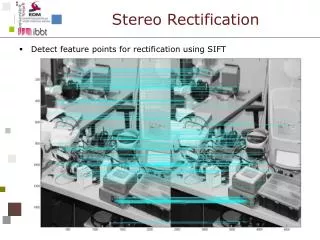
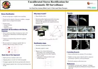
Image Rectification for Stereo Vision. Charles Loop Zhengyou Zhang Microsoft Research. Problem Statement. Compute a pair of 2D projective transforms ( homographies ). rectification. Original images. Rectified images. Motivations. To simplify stereo matching:

E N D
Image Rectification for Stereo Vision Charles Loop Zhengyou Zhang Microsoft Research
Problem Statement • Compute a pair of 2D projective transforms (homographies) rectification Original images Rectified images
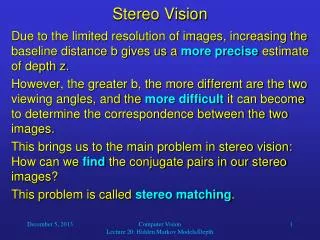
Motivations • To simplify stereo matching: Instead of comparing pixels on skew lines, we now only compare pixels on the same scan lines. • Graphics applications: view morphing • Problem: Rectifying homographies are not unique • Goal: to develop a technique based on geometrically well-defined criteria minimizing image distortion due to rectification
Epipolar Geometry M m m’ C C’ Epipole at Fundamental matrix • Epipoles anywhere • Fundamental matrix F: a 3x3 rank-2 matrix
Stereo Image Rectification • Compute H and H’ such that • Compute rectified image points: • Problem: H and H’ are not unique.
Properties of H and H’ (I) • Consider each row of H and H’ as a line: • Recall: both e and e’ are sent to [1 0 0]T • Observations (I): • v and w must go through the epipole e • v’ and w’ must go through the epipole e’ • u and u’ are irrelevant to rectification
Properties of H and H’ (II) • Observation (II): Lines v and v’, and lines w and w’ must be corresponding epipolar lines. • Observation (III): Lines w and w’ define the rectifying plane.
Decomposition of H • Special projective transform: • Similarity transform: • Shearing transform:
Special Projective Transform (I) • Sends the epipole to infinity • epipolar lines become parallel • Captures all image distortion due to projective transformation • Subgoal: Make Hp as affine as possible.
Special Projective Transform (II) How to do it? • Let original image point be • the transformed point will be • Observation: If all weights are equal, then there is no distortion. • Key idea: minimize the variation of wi over all pixels with weight
Similarity Transform • Rotate and translate images such that the epipolar lines are horizontally aligned. • Images are now rectified.
Shearing Transform • Free to scale and translate in the horizontal direction. • Subgoal: Preserve original image resolution as close as possible.
Example • Original image pair
Intermediate result • After special projective transform:
Intermediate result • After similarity transform:
Final result • After shearing transform