Download
1 / 12
120 likes | 168 Views
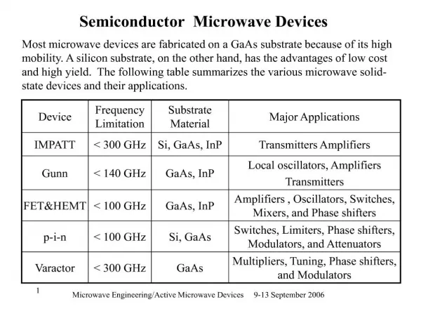
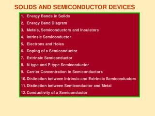
SOLIDS AND SEMICONDUCTOR DEVICES - II. PN Junction Diode Forward Bias of Junction Diode Reverse Bias of Junction Diode Diode Characteristics Static and Dynamic Resistance of a Diode Diode as a Half Wave Rectifier Diode as a Full Wave Rectifier.

E N D
SOLIDS AND SEMICONDUCTOR DEVICES - II • PN Junction Diode • Forward Bias of Junction Diode • Reverse Bias of Junction Diode • Diode Characteristics • Static and Dynamic Resistance of a Diode • Diode as a Half Wave Rectifier • Diode as a Full Wave Rectifier Created by C. Mani, Principal, K V No.1, AFS, Jalahalli West, Bangalore
PN Junction Diode: + + + + + + + + + + + + + + + + P N - - - - - - - - - - - - - - - - When a P-type semiconductor is joined to a N-type semiconductor such that the crystal structure remains continuous at the boundary, the resulting arrangement is called a PN junction diode or a semiconductor diode or a crystal diode. Mobile Hole (Majority Carrier) When a PN junction is formed, the P region has mobile holes (+) and immobile negatively charged ions. N region has mobile electrons (-) and immobile positively charged ions. Immobile Negative Impurity Ion Mobile Electron (Majority Carrier) Immobile Positive Impurity Ion The whole arrangement is electrically neutral. For simplicity, the minority charge carriers are not shown in the figure.
PN Junction Diode immediately after it is formed : V + + + Depletion region - - - - - - - - - - - - - - - E P N + + + + Fr + + + + + + + + Fr • After the PN junction diode is formed – • Holes from P region diffuse into N region due to difference in concentration. • Free electrons from N region diffuse into P region due to the same reason. • Holes and free electrons combine near the junction. • Each recombination eliminates an electron and a hole. • The uncompensated negative immobile ions in the P region do not allow any more free electrons to diffuse from N region. • The uncompensated positive immobile ions in the N region do not allow any more holes to diffuse from P region.
vii) The positive donor ions in the N region and the negative acceptor ions in the P region are left uncompensated. • viii)The region containing the uncompensated acceptor and donor ions is called ‘depletion region’ because this region is devoid of mobile charges. • Since the region is having only immobile charges, therefore, this region is also called ‘space charge region’. • The N region is having higher potential than P region. • So, an electric field is set up as shown in the figure. • The difference in potential between P and N regions across the junction makes it difficult for the holes and electrons to move across the junction. This acts as a barrier and hence called ‘potential barrier’ or ‘height of the barrier’. • The physical distance between one side and the other side of the barrier is called ‘width of the barrier’. • Potential barrier for Si is nearly 0.7 V and for Ge is 0.3 V. • The potential barrier opposes the motion of the majority carriers. • xv) However, a few majority carriers with high kinetic energy manage to overcome the barrier and cross the junction. • Potential barrier helps the movement of minority carriers.
Forward Bias: V P N + + + + + + + + + + + + + + + + + + + + + + + + + + + + + + - - - - - - - - - - - - - - - - - - - - - - - - - - - - - - E E E P Ih N Ie Depletion region When the positive terminal of the battery is connected to P-region and negative terminal is connected to N-region, then the PN junction diode is said to be forward-biased. • Holes in P-region are repelled by +ve terminal of the battery and the free electrons are repelled by –ve terminal of the battery. • So, some holes and free electrons enter into the depletion region. • The potential barrier and the width of the depletion region decrease. • Therefore, a large number of majority carriers diffuse across the junction. • Hole current and electronic current are in the same direction and add up.
Once they cross the junction, the holes in N-region and the electrons in P-region become minority carriers of charge and constitute minority current. • For each electron – hole recombination, an electron from the negative terminal of the battery enters the N-region and then drifts towards the junction. • In the P-region, near the positive terminal of the battery, an electron breaks covalent bond in the crystal and thus a hole is created. The hole drifts towards the junction and the electron enters the positive terminal of the battery. • vii) Thus, the current in the external circuit is due to movement of electrons, current in P-region is due to movement of holes and current in N-region is due to movement of electrons. • viii) If the applied potential is increased, the potential barrier further decreases. As a result, a large number of majority carriers diffuse through the junction and a larger current flows.
Reverse Bias: V V P N + + + + + + + + + + + + + + + + + + + + + + + + + + + + + + - - - - - - - - - - - - - - - - - - - - - - - - - - - - - - E E E Ih P N Ie Depletion region When the negative terminal of the battery is connected to P-region and positive terminal is connected to N-region, then the PN junction diode is said to be reverse-biased. • Holes in P-region are attracted by -ve terminal of the battery and the free electrons are attracted by +ve terminal of the battery. • Thus, the majority carriers are pulled away from the junction. • The potential barrier and the width of the depletion region increase. • Therefore, it becomes more difficult for majority carriers diffuse across the junction.
But the potential barrier helps the movement of the minority carriers. As soon as the minority carriers are generated, they are swept away by the potential barrier. • At a given temperature, the rate of generation of minority carriers is constant. • So, the resulting current is constant irrespective of the applied voltage. For this reason, this current is called ‘reverse saturation current’. • Since the number of minority carriers is small, therefore, this current is small and is in the order of 10-9 A in silicon diode and 10-6 A in germanium diode. • The reverse – biased PN junction diode has an effective capacitance called ‘transition or depletion capacitance’. P and N regions act as the plates of the capacitor and the depletion region acts as a dielectric medium.
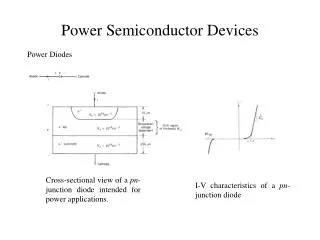
Diode Characteristics: If (mA) D Vr (Volt) VB Vk + + + + V V μA mA Ir (μA) D Forward Bias: Linear Region 0 Vf (Volt) Vk – Knee Voltage VB – Breakdown Voltage Reverse Bias: Resistance of a Diode: • Static or DC Resistance Rd.c = V / I • Dynamic or AC Resistance • Ra.c = ΔV / ΔI
PN Junction Diode as a Half Wave Rectifier: ● ● ● ● ● ● ● ● ● ● ● ● D RL D RL + D The process of converting alternating current into direct current is called ‘rectification’. The device used for rectification is called ‘rectifier’. The PN junction diode offers low resistance in forward bias and high resistance in reverse bias. RL No output +
PN Junction Diode as a Full Wave Rectifier: + ● ● ● ● ● ● ● ● ● ● ● ● D1 RL A B D2 D1 RL A B D2 D1 RL When the diode rectifies whole of the AC wave, it is called ‘full wave rectifier’. During the positive half cycle of the input ac signal, the diode D1 conducts and current is through BA. During the negative half cycle, the diode D2 conducts and current is through BA. A B D2 +
Special Purpose p-n Junction Diodes: If (mA) Vr (Volt) VZ 0 Vf (Volt) ● Vz – Breakdown Voltage RS Ir (μA) Unregulated Voltage VL ● Regulated Voltage VZ RL ● ● Zener Diode • Heavily doped • Depletion Region is < 10-6 m • Electric Field is very high (5x10⁶ V/m) • Reverse biased • Internal Field emission or field ionisation Zener Diode as a Voltage Regulator End of S & SC - II