Download
1 / 18
240 likes | 745 Views
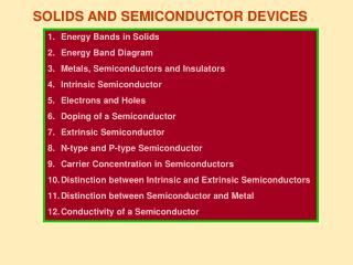
SOLIDS AND SEMICONDUCTOR DEVICES - I. Energy Bands in Solids Energy Band Diagram Metals, Semiconductors and Insulators Intrinsic Semiconductor Electrons and Holes Doping of a Semiconductor Extrinsic Semiconductor N-type and P-type Semiconductor Carrier Concentration in Semiconductors

E N D
SOLIDS AND SEMICONDUCTOR DEVICES - I • Energy Bands in Solids • Energy Band Diagram • Metals, Semiconductors and Insulators • Intrinsic Semiconductor • Electrons and Holes • Doping of a Semiconductor • Extrinsic Semiconductor • N-type and P-type Semiconductor • Carrier Concentration in Semiconductors • Distinction between Intrinsic and Extrinsic Semiconductors • Distinction between Semiconductor and Metal • Conductivity of a Semiconductor
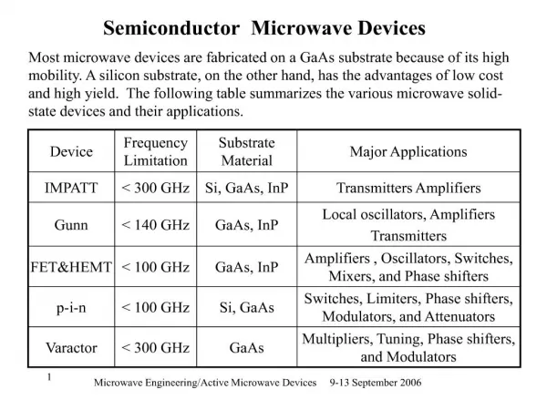
Energy Bands in Solids • According to Quantum Mechanical Laws, the energies of electrons in a free atom can not have arbitrary values but only some definite (quantized) values. • However, if an atom belongs to a crystal, then the energy levels are modified. • This modification is not appreciable in the case of energy levels of electrons in the inner shells (completely filled). • But in the outermost shells, modification is appreciable because the electrons are shared by many neighbouring atoms. • Due to influence of high electric field between the core of the atoms and the shared electrons, energy levels are split-up or spread out forming energy bands. Consider a single crystal of silicon having N atoms. Each atom can be associated with a lattice site. Electronic configuration of Si is 1s2, 2s2, 2p6,3s2, 3p2. (Atomic No. is 14)
Formation of Energy Bands in Solids Energy Conduction Band • • 3p2 • • Forbidden Energy Gap 3s2 Valence Band • • • • • • 2p6 Ion core state • • 2s2 • • 1s2 O a b c Inter atomic spacing (r) d
r = Od (>> Oa): Each of N atoms has its own energy levels. The energy levels are identical, sharp, discrete and distinct. The outer two sub-shells (3s and 3p of M shell or n = 3 shell) of silicon atom contain two s electrons and two p electrons. So, there are 2N electrons completely filling 2N possible s levels, all of which are at the same energy. Of the 6N possible p levels, only 2N are filled and all the filled p levels have the same energy. (ii) Oc < r < Od: There is no visible splitting of energy levels but there develops a tendency for the splitting of energy levels. (iii) r = Oc: The interaction between the outermost shell electrons of neighbouring silicon atoms becomes appreciable and the splitting of the energy levels commences. (iv) Ob < r < Oc: The energy corresponding to the s and p levels of each atom gets slightly changed. Corresponding to a single s level of an isolated atom, we get 2N levels. Similarly, there are 6N levels for a single p level of an isolated atom.
Since N is a very large number (≈ 1029 atoms / m3) and the energy of each level is of a few eV, therefore, the levels due to the spreading are very closely spaced. The spacing is ≈ 10-23 eV for a 1 cm3 crystal. The collection of very closely spaced energy levels is called anenergy band. (v) r = Ob: The energy gap disappears completely. 8N levels are distributed continuously. We can only say that 4N levels are filled and 4N levels are empty. (v) r = Oa: The band of 4N filled energy levels is separated from the band of 4N unfilled energy levels by an energy gap called forbidden gap or energy gap or band gap. The lower completely filled band (with valence electrons) is called the valence band and the upper unfilled band is called the conduction band. • Note: • The exact energy band picture depends on the relative orientation of atoms in a crystal. • If the bands in a solid are completely filled, the electrons are not permitted to move about, because there are no vacant energy levels available.
Metals The first possible energy band diagram shows that the conduction band is only partially filled with electrons. With a little extra energy the electrons can easily reach the empty energy levels above the filled ones and the conduction is possible. • • • • • • Partially filled Conduction Band Conduction Band • • • • • • The second possible energy band diagram shows that the conduction band is overlapping with the valence band. This is because the lowest levels in the conduction band needs less energy than the highest levels in the valence band. The electrons in valence band overflow into conduction band and are free to move about in the crystal for conduction. Valence Band The highest energy level in the conduction band occupied by electrons in a crystal, at absolute 0 temperature, is called Fermi Level. The energy corresponding to this energy level is called Fermi energy. If the electrons get enough energy to go beyond this level, then conduction takes place.
Eg - The fraction is p α e kB T Semiconductors At absolute zero temperature, no electron has energy to jump from valence band to conduction band and hence the crystal is an insulator. At room temperature, some valence electrons gain energy more than the energy gap and move to conduction band to conduct even under the influence of a weak electric field. Conduction Band Forbidden Energy Gap ≈1 eV • • • • • • • • Valence Band Eg-Si = 1.1 eV EgGe= 0.74 eV Since Eg is small, therefore, the fraction is sizeable for semiconductors. As an electron leaves the valence band, it leaves some energy level in band as unfilled. Such unfilled regions are termed as ‘holes’ in the valence band. They are mathematically taken as positive charge carriers. Any movement of this region is referred to a positive hole moving from one position to another.
Insulators Conduction Band • • • • • • Valence Band Electrons, however heated, can not practically jump to conduction band from valence band due to a large energy gap. Therefore, conduction is not possible in insulators. Forbidden Energy Gap ≈6 eV Eg-Diamond = 7 eV Electrons and Holes On receiving an additional energy, one of the electrons from a covalent band breaks and is free to move in the crystal lattice. While coming out of the covalent bond, it leaves behind a vacancy named ‘hole’. An electron from the neighbouring atom can break away and can come to the place of the missing electron (or hole) completing the covalent bond and creating a hole at another place. The holes move randomly in a crystal lattice. The completion of a bond may not be necessarily due to an electron from a bond of a neighbouring atom. The bond may be completed by a conduction band electron. i.e., free electron and this is referred to as ‘electron – hole recombination’.
Valence electrons Covalent Bond Broken Covalent Bond Free electron ( - ) Ge Ge Ge Ge Ge Ge Ge Ge Ge Ge Ge Ge Ge Ge Ge Ge Hole ( + ) Intrinsic or Pure Semiconductor C.B + Eg 0.74 eV V.B + + Heat Energy
Intrinsic Semiconductor is a pure semiconductor. The energy gap in Si is 1.1 eV and in Ge is 0.74 eV. Si: 1s2, 2s2, 2p6,3s2, 3p2. (Atomic No. is 14) Ge: 1s2, 2s2, 2p6,3s2, 3p6, 3d10, 4s2, 4p2. (Atomic No. is 32) In intrinsic semiconductor, the number of thermally generated electrons always equals the number of holes. So, if ni and pi are the concentration of electrons and holes respectively, then ni = pi.The quantity ni or pi is referred to as the ‘intrinsic carrier concentration’. Doping a Semiconductor Doping is the process of deliberate addition of a very small amount of impurity into an intrinsic semiconductor. The impurity atoms are called ‘dopants’. The semiconductor containing impurity is known as ‘impure or extrinsic semiconductor’. • Methods of doping: • Heating the crystal in the presence of dopant atoms. • Adding impurity atoms in the molten state of semiconductor. • Bombarding semiconductor by ions of impurity atoms.
Extrinsic or Impure Semiconductor C.B 0.045 eV Ge Ge Ge Ge Ge Ge Ge Ge Eg = 0.74 eV As V.B Donor level N - Type Semiconductors - + + When a semiconductor of Group IV (tetra valent) such as Si or Ge is doped with a penta valent impurity (Group V elements such as P, As or Sb), N – type semiconductor is formed. When germanium (Ge) is doped with arsenic (As), the four valence electrons of As form covalent bonds with four Ge atoms and the fifth electron of As atom is loosely bound.
The energy required to detach the fifth loosely bound electron is only of the order of 0.045 eV for germanium. A small amount of energy provided due to thermal agitation is sufficient to detach this electron and it is ready to conduct current. The force of attraction between this mobile electron and the positively charged (+ 5) impurity ion is weakened by the dielectric constant of the medium. So, such electrons from impurity atoms will have energies slightly less than the energies of the electrons in the conduction band. Therefore, the energy state corresponding to the fifth electron is in the forbidden gap and slightly below the lower level of the conduction band. This energy level is called ‘donor level’. The impurity atom is called ‘donor’. N – type semiconductor is called ‘donor – type semiconductor’.
Carrier Concentration in N - Type Semiconductors When intrinsic semiconductor is doped with donor impurities, not only does the number of electrons increase, but also the number of holes decreases below that which would be available in the intrinsic semiconductor. The number of holes decreases because the larger number of electrons present causes the rate of recombination of electrons with holes to increase. Consequently, in an N-type semiconductor, free electrons are the majority charge carriers and holes are the minority charge carriers. If n and p represent the electron and hole concentrations respectively in N-type semiconductor, then n p = ni pi = ni2 where ni and pi are the intrinsic carrier concentrations. The rate of recombination of electrons and holes is proportional to n and p.Or, the rate of recombination is proportional to the product np.Since the rate of recombination is fixed at a given temperature, therefore, the product np must be a constant. When the concentration of electrons is increased above the intrinsic value by the addition of donor impurities, the concentration of holes falls below its intrinsic value, making the product np a constant, equal to ni2.
C.B Ge Ge Ge Ge Ge Ge Ge Ge Eg = 0.74 eV 0.05 eV In V.B Acceptor level P - Type Semiconductors + + When a semiconductor of Group IV (tetra valent) such as Si or Ge is doped with a tri valent impurity (Group III elements such as In, B or Ga), P – type semiconductor is formed. When germanium (Ge) is doped with indium (In), the three valence electrons of In form three covalent bonds with three Ge atoms. The vacancy that exists with the fourth covalent bond with fourth Ge atom constitutes a hole.
The hole which is deliberately created may be filled with an electron from neighbouring atom, creating a hole in that position from where the electron jumped. Therefore, the tri valent impurity atom is called ‘acceptor’. Since the hole is associated with a positive charge moving from one position to another, therefore, this type of semiconductor is called P – type semiconductor. The acceptor impurity produces an energy level just above the valence band. This energy level is called ‘acceptor level’. The energy difference between the acceptor energy level and the top of the valence band is much smaller than the band gap. Electrons from the valence band can, therefore, easily move into the acceptor level by being thermally agitated. P – type semiconductor is called ‘acceptor – type semiconductor’. In a P – type semiconductor, holes are the majority charge carriers and the electrons are the minority charge carriers. It can be shown that, n p = ni pi = ni2
Electrical Conductivity of Semiconductors E 1 = e (neve + nhvh) ρ ρ V = neeAve + nheAvh V since E = R l V A Or = eA (neve + nhvh) ρl ρl R = = e (neμe + nhμh) A since Ih Ie I = Ie + Ih Ie = neeAve Ih = nheAvh So, I = neeAve + nheAvh If the applied electric field is small, then semiconductor obeys Ohm’s law. I E = eA (neve + nhvh) Mobility (μ) is defined as the drift velocity per unit electric field. • Note: • The electron mobility is higher than the hole mobility. • The resistivity / conductivity depends not only on the electron and hole densities but also on their mobilities. • The mobility depends relatively weakly on temperature. σ= e (neμe + nhμh) Or