Download
1 / 25
340 likes | 770 Views
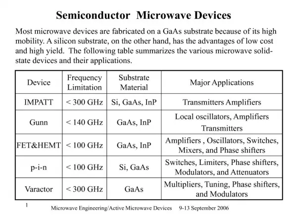
EE201 SEMICONDUCTOR DEVICES. MOHD ZULHILMI JAAFAR JABATAN KEJURUTERAAN ELEKTRIK POLITEKNIK KUALA TERENGGANU. SEMICONDUCTOR MATERIAL.

E N D
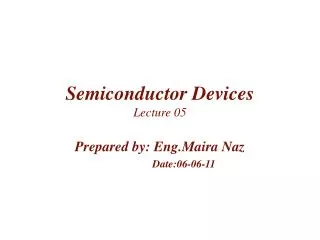
EE201SEMICONDUCTOR DEVICES MOHD ZULHILMI JAAFAR JABATAN KEJURUTERAAN ELEKTRIK POLITEKNIK KUALA TERENGGANU
SEMICONDUCTOR MATERIAL • • The term conductor is applied to any material that will support a generous flow of charge when a voltage source of limited magnitude is applied across its terminals. • • An insulator is a material that offers a very low level of • conductivity under pressure from an applied voltage • source. • • A semiconductor (SC) therefore, is a material that has a conductivity level somewhere between the extremes of an insulator an a conductor.
ATOM STRUCTURE • • Bohr Atom Structure was first introduced by Niels Bohr (1913). • • Examine the structure of an atom; atom is composed of 3 basic particles: the electron, the proton, and the neutron. • • In the atomic lattice, the neutrons and protons form the nucleus, while the electrons revolve around the nucleus in a fixed orbit. • • The Bohr models of the 2 most commonly used semiconductor (SC): Ge and Si are shown as followed: Silicon Germanium Figure 1.1
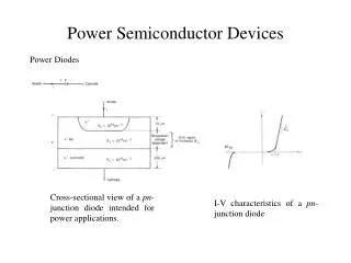
COVALENT BONDING • Covalent bonds are formed bythe sharing of valence electrons with neighboring atoms. • Fig. 1.1 shows how each Si atom with four adjacent atoms to form a Si crystal. A Si atom with its 4 valence e- shares an e- with each of its 4 neighbour. • This effectively creates 8 valence e- for each atom & produces a state of chemical stability.
Ge atom has 32 orbiting e-, while Si has 14 orbiting e-. • In each case, there are 4 e- in the outermost shell. • The potential required to remove any one of these 4 valence e- is lower than that required for any other e- in the structure. • In a pure Ge & Si crystal these 4 valence e- are bonded to 4 adjoining atoms as shown in the following figure. Figure 1.2
CONDUCTION ELECTRONS & HOLES • When e- jumps to the CB, a vacancy is left in the valence band within the crystal. This vacancy is called a hole. • Hole also referred as positive charge carrier. • Foe every e- raised to the CB by external energy, there is 1 hole left in the valence band, creating what is called electron–hole pair (EHP). • Recombination occurs when a CB e- loses energy & falls back into a hole in the valence band. • To summarize, a peace of intrinsic Si at room temperature has, at any instant a no. of CB (free) e- that are unattached to any atom & are essentially drifting randomly throughout the material. Also an equal no. of holes are created in the valence band when these electrons jump into the CB
ENERGY LEVEL • In the atomic structure there are discrete energy levels associated with each orbitting e-. • The more distant the e- from the nucleus, the higher the energy state and any e- that has left its parent atom has a higher energy state than any e- in the atomic structure. • Between the discrete energy levels are gaps in which no e- in the isolated atomic structure can appear. Figure 1.3
Note that there are boundary levels & max. energy states in which any e- in the atomic lattice can find itself, and there remains a forbidden region between the valence band & the ionization level. • Recall that ionization is the mechanism whereby an e- can absorb sufficient energy to break away from atomic structure & enter the conduction band (CB). • Energy associated with each e- is measured in eV 4 • Since energy is also measured in joules & the charge of one e- =1.6 x 10⁻¹⁹ coulomb, W = QV = (1.6 x 10⁻¹⁹ C) (1 V) Q= charge associated with single current * 1eV = 1.6 x 10⁻¹⁹ J
ENERGY LEVEL COMPARISON Figure 1.4
INSULATOR • The energy diagram for the insulator shows the insulator with a very wide energy gap. The wider this gap, the greater the amount of energy required to move the electron from the valence band to the conduction band. • Therefore, an insulator requires a large amount of energy to obtain a small amount of current. The insulator "insulates” because of the wide forbidden band or energy gap.
SEMICONDUCTOR • The semiconductor, on the other hand, has a smaller forbidden band and requires less energy to move an electron from the valence band to the conduction band. • Therefore, for acertain amount of applied voltage, more current will flow in the semiconductor than in the insulator.
CONDUCTOR/METAL • The last energy level is for a conductor. • Notice, there is no forbidden band or energy gap and the valence and conduction bands overlap. • With no energy gap, it takes a small amount or energy gap and the valence and conduction bands overlap. • With no energy gap, it takes a small amount easily.
INTRINSIC MATERIAL • Intrinsic material is the pure semiconductor that has no any additional elements. Examples : Silicon & Germanium. • Intrinsic Semiconductor has no advantages.
EXTRINSIC MATERIAL • Because Si is the material used most frequently as the base material in construction of solid state electronic device, the discussion to follow in this & the next few sections deals solely with Si SC. • Extrinsic Material: material that has been subjected to the doping process. • There are 2 types of Extrinsic Material: n-type & p-type. • Both materials are formed by adding a predetermined no. of impurity atoms to a Si base. • n-type: created by introducing impurity elements that have 5 valence e- (eg. As & P). • p-type: formed by doping a pure Ge or Si crystal with impurity atoms having 3 valence e- (eg. B, Al, In & Ga).
Si Si Si Si Si Si Ar Si Si Si Figure 1.5 Silicon doped with Arsenic N-TYPE MATERIAL • Happens when pure semiconductor (exp: Silicon) doped with pentavalent atom (has 5 e.v)(refer Fig. 1.3): • Four out of five electron valence from pentavalent atom formed covalent bond with silicon atoms but there is an electron that has no pair • This electron will escape from its orbit and become free electron, negative current carrier. More pentavalent atoms more free electrons, thus more negative current carriers.Therefore this material is called N-type material. • At very low temperature, majority current carriers are free electrons. • At room temperature, a few holes produced and called minority current carriers Free Electron from arsenic atom that has no pair
Si Si Si Si Si Si In Si Si Si Figure 1.6 Silicon doped with Indium P-TYPE MATERIAL • P- type material formed when pure semiconductor doped with trivalent atom. (Figure 1.4) • Three electron valences form covalent bond but another one has no pair. This situation creates hole, positive current carrier. • More trivalent atoms, more holes, thus more negative current carriers, therefore this material is called P-type material. • At very low temperature, majority current carriers are holes and at very high temperature, minority current carriers are electrons hole
PN JUNCTION • One of the crucial keys to solid state electronics is the nature of the P-N junction. When p-type and n-type materials are placed in contact with each other, the junction behaves very differently than either type of material alone. • Specifically, current will flow readily in one direction (forward biased) but not in the other (reverse biased), creating the basic diode. This non-reversing behavior arises from the nature of the charge transport process in the two types of materials.
The open circles on the left side of the junction above represent "holes" or deficiencies of electrons in the lattice which can act like positive charge carriers. • The solid circles on the right of the junction represent the available electrons from the n-type dopant. • Near the junction, electrons diffuse across to combine with holes, creating a "depletion region".
DEPLETION REGION • When a p-n junction is formed, some of the free electrons in the n-region diffuse across the junction and combine with holes to form negative ions. In so doing they leave behind positive ions at the donor impurity sites. Figure 1.8
THRESHOLD VOLTAGE The process of combination electrons and holes continues until threshold voltage produced, 0.7 V for silicon and 0.3 V for germanium, Figure 1.9
PN JUNCTION BIAS • Voltage is supplied to both ends of the junction to give bias. • There are two types of bias, forward bias and reverse bias
FORWARD BIAS • Forward bias is shown in Figure 1.10 where negative probe power supply is connected to n-type material and positive probe power supply is connected to p-type material. • This situation will decrease the size of depletion region. This occurs because negative probe power supply will push the electrons in n-type material and the positive probe power supply will push holes in p –type material. • The current produced is called forward current. Figure 1.10
Figure 1.11 shows both current carries move and finally surpassing the voltage limit (threshold voltage) at the depletion region. • Power supply has to surpass the voltage limit, 0.7V for silicon and 0.3V for germanium before flowing Figure 1.11
REVERSE BIAS • Figure 1.12 shows PN junction is reverse-biased where negative probe power supply is connected to p-type material and positive probe power supply is connected to n-type material. • This situation will increase the size of depletion region. This occurs because negative probe power supply will attract the electrons in n-type material and the positive probe power supply will attract holes in p –type material. • There is a very small current produced which is called reverse current but can be ignored. • When the power supply is increased instantly, it will break the junction and will blow the component. The voltage is called breakdown voltage. Figure 1.12