Download
1 / 99
1.04k likes | 1.24k Views
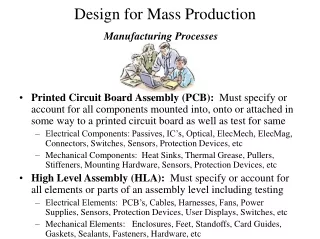
Digital Material Deposition for Product Manufacturing Processes. Purpose of Presentation. Provide an overview of how the digital printing technologies utilized in the reprographics industry for over 50 years have been used for: Unusual printing applications

E N D
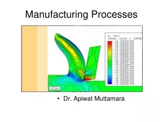
Digital Material Deposition for Product Manufacturing Processes
Purpose of Presentation • Provide an overview of how the digital printing technologies utilized in the reprographics industry for over 50 years have been used for: • Unusual printing applications • Special material deposition applications Material Deposition Presentation
What is Digital Material Deposition? • The preparation of materials to make them suitable for digital deposition • The means (process, hardware, and controls) to enable the controlled lay-down of materials onto various substrates: • Practiced in the reprographics industry for over 50 years as copying & printing • Processes and technologies have now been applied to a wide variety of non-printing applications Material Deposition Presentation
Applications of Digital Deposition • The technologies of digital printing are being used to: • Make products • Print on products • Coat products • Print on product containers • Print on packaging • Print labels Material Deposition Presentation
Advantages of Digital Deposition • Precise & controlled amounts of material lay-down • Mass • Thickness • Selectively variable process • Change amounts and placement at will • Create images - monochrome to full color • Layered construction • High value material capability • Little to no material wastage • Readily scalable • From laboratory, to pilot, to production • Short-run to long-run • Narrow to wide format • 3-Dimensional applications Material Deposition Presentation
Potential Disadvantages of Digital Deposition Technology • Some systems can be complex • Sometimes material latitudes are limited • May be more costly on a cost per unit basis than long-run conventional processes • Offset • Blade coating • Pad printing Material Deposition Presentation
The Primary Forms of Deposition Materials • Deposition Materials can be : • Liquid materials or • Dry powder materials or • Dry film materials Material Deposition Presentation
Widely Practiced Reprographic Deposition (Printing) Systems • Electrostatic (Dry powder and liquid) • Electrophotography • Electrography • Inkjet (Liquid) • Drop on Demand • Thermal & Piezoelectric • Continuous • Thermal (Dry film) • Direct & Transfer • Magnetographic (Dry powder) Material Deposition Presentation
Digital Deposition Processes Latent Image Intermediate Direct-to- Receiver Special Process Receiver Media Electrophotography Ionography Electrography Magnetography Drop on Demand IJ Continuous IJ Thermal Transfer Toner Jet Dry Silver Thermal Paper Electrostatographic UV Light Sensitive Digital Deposition Processes Overview Material Deposition Presentation
Major Segmentation of Deposition Technologies • Deposition system • Direct versus Indirect • Material properties • Liquid versus Dry Material Deposition Presentation
Major Segmentation Map Material Deposition Presentation
Liquid vs. Dry • Conventional thinking for dispensing, dosing, metering: • Liquid deposition via inkjet technology • The ‘de facto approach’ • However, liquid AND dry powder materials can be digitally deposited • Highly application dependent Material Deposition Presentation
Liquid Deposition & Micro-dispensing Material Deposition Presentation
Printhead Roadmap Continuous Drop-on-Demand Piezoelectric Electrostatic Acoustic Thermal Multiple Deflection Hollow Tube Edge shooter Single Jet Multi-Jet Roof shooter Bending Plate Binary Deflection Extending Member Hertz Mist Shear Mode Magnetic Deflection Material Deposition Presentation
Inkjet Implementation: Fluid Issues Fluid physical attributes and chemistry drive the system design: • Aqueous or non-aqueous • Chemically reactive with print head • Viscosity versus temperature • Surface tension • pH • Volatility • Fluid temperature constraints • Fluid formulation modification latitude • Particulate size Material Deposition Presentation
Inkjet Implementation: Head Issues • All inkjet head types are possible candidates • Head matched to the fluid and application: • Ejected volume and nozzle count requirements • Jetting frequency requirement • Throw distance and direction • Number of unique fluid types required • Head maintenance algorithms and hardware • Ambient environment • Reliability and operator interaction constraints Material Deposition Presentation
Inkjet Implementation: Substrate Issues • Like the fluid, the substrate is typically a given and influences the integration: • x and y motion requirements • Speed, step size, and precision • Mounting and alignment • Topography considerations • Substrate - Fluid interactions Material Deposition Presentation
Inkjet Implementation: Other Challenges • Head-drive electronics and algorithms • Data source and manipulation requirements • Environmental concerns • Temperature and humidity • Outside contaminants • Process effluents • Drying Material Deposition Presentation
Example:Polymer Electronics - Displays Ejection of electro-luminescent polymer onto glass substrate for monochrome or color displays ADVANTAGE • Inexpensive • Automated • Repeatable • “Displays-on- Demand”
Example:Polymer Electronics - Sensors Ejection of “environmentally sensitive” polymer onto silicon or advanced PCB substrate ADVANTAGE • Inexpensive • Automated • Repeatable • “Sensors-on- Demand”
Example: Rapid Prototyping – SLA Substitute Layer-upon-layer fluid ejection to build computer-generated, three-dimensional parts and prototypes. ADVANTAGE • Inexpensive • Automated • Repeatable • “Parts-on-Demand” Material Deposition Presentation
Manufacturing Dispensing Examples Flexible adhesive placement, coating, soldering, and precise patterning for in-line and off-line production ADVANTAGE • Automated • Repeatable • Quantity-controlled dispensing Material Deposition Presentation
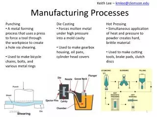
Example: Manufacturing – Dispensing Solder 25µm bumps of 63/37 solder deposited on 35µm pitch using “Solder Jet” technology Material Deposition Presentation
Example: Pharmaceutical – Dispense Active Agent • Advanced drug-dispensing system • Active agent(s) stored in carrier wells that are filled on demand by specialized inkjet heads ADVANTAGE • Increased medical control over drug application • Drugs tailored to individual’s medical requirements
Example: Biotechnology – DNA Testing • HP partnership with Affymetrix Gene Chip • Dispensing of “tiny DNA segments, housed inside picoliter-size droplets of liquid … onto an array of integrated circuit-like chips…” Source: Upside, Sept. 23, 1998 (www.upside.com) ADVANTAGE • Automated procedures • Repeatable results
Example: Medical - Containment Hydrophobic material forms barrier to contain biological fluids or other fluids for tissue preparation ADVANTAGE • Automated • Pattern retention • Repeatable processes
A Case Study – Liquid Deposition • Precision coating of a medical device for drug loading • Project performed by Xactiv Inc, www.xactiv.com (formerly Torrey Pines Research) • The development activity was carried out on behalf of a client Material Deposition Presentation
Case Study – Stent Coating • Stent – small, lattice-shaped, metal tube that is inserted permanently into an artery. The stent helps hold open an artery so that blood can flow through it. Material Deposition Presentation
Case Study – Stent Coating Requirements • Drug eluting stent is coated with polymer that incorporates a drug that helps prevent plaque build-up • Drug elutes very slowly over a period of years • Coating must be applied uniformly on inside and outside of stent • Coating thickness must be very uniform (+/- 5%) • Coating weight stent to stent must be well controlled (+/- 5%) • Stents of various diameters and lengths Material Deposition Presentation
Case Study – Stent Coating Challenges • Coating materials pre-defined by client • Polymer has few viable solvents • Stent must be coated all over while handling • Precision requirement • Minimize wastage • Speed Material Deposition Presentation
Case Study – Stent Coating Solution • Piezo industrial drop on demand system selected • Dimatix S-series print head • Resistant to solvents • Precision jetting system • TPR modified the print head • Replaced seals Material Deposition Presentation
Case Study – Stent Coating Solution • Piezo drop on demand industrial print head • Modified seals to withstand solvent • Custom designed stent handling system • Custom designed precision inkjet coating system • Special maintenance algorithms and maintenance system • Eliminate nozzle blockage due to drying • Solvent resistant fluid handling • Solvent chemistry • Ink development Material Deposition Presentation
Case Study – Stent Coating • Precision stent handling system Material Deposition Presentation
Case Study – Stent Coating • Precision inkjet coating system Material Deposition Presentation
Case Study – Stent Coating System Material Deposition Presentation
Dry Powder Deposition Material Deposition Presentation
Electrostatic Dry Powder Deposition Typical Application Requirements • Dry powder materials • From ~ 5 to 75 microns in size • Solvent-less process • High area coverage - usually • Large volumes of material • Precise metering/thickness control • Uniform coating • Static or variable information • Contact or non-contact process • Direct or indirect process • 2D or 3D deposition Material Deposition Presentation
Conventional Powder Coating Charging air gun Typical powder spray system Material Deposition Presentation
Conventional Powder Coating Problems/Limitations • Corona or tribo charging with air transport • Poor powder charging • Poor directional control • Air overwhelms electric field and wastes material • Requires substantial post “clean-up” • Uniformity not assured • Masking difficult • Images with information impossible Material Deposition Presentation
The Challenges of Electrostatic Powder Development • Using/modifying or creating the materials for: • Functional requirements of application • Charging • Transport • Identifying a suitable powder Development Sub-system technology • Direct versus Indirect architecture • Dealing with Substrate properties • Often a given Material Deposition Presentation
Important Powder Properties • Dielectric properties • Insulative versus conductive • Magnetic properties • Powder size and size distribution • Electrostatic charging characteristics • Rheological (melt) properties • Flow properties • Functional characteristics • Color • Application dependent functionality Material Deposition Presentation
Important Substrate Properties • Dielectric properties • Insulative versus conductive • Flat or 3D • If flat • Sheet vs. roll stock • Flatness tolerance • If 3D • Shape and 3D depth • Layered construction characteristics • Hard vs. soft characteristics Material Deposition Presentation
Powder Properties Conductive Insulative Magnetic Non-magnetic Substrate Properties Charging Method Conductive Insulative Triboelectrification Induction Deposition Method Direct Transfer Dry Powder Deposition System Considerations Material Deposition Presentation
What are Conductive Materials • It depends on time for current to flow: • With copper – not very long • With fused quartz - sit down because you’re going to be there a while • Conductivity represents a continuum Material Deposition Presentation
Conductivity is a Continuum • In conductors, electric charges are free to move • In an insulator, charges are less free to move • There’s no such thing as a perfect insulator • However, insulating ability of fused quartz is 1025 times that of copper • Conductivity is characterized by a physical property - Resistivity Semi-conductive Materials Conductive Materials Insulative Materials Material Deposition Presentation
Resistivity of a ‘Conductive’ Material A conductive material for many electrostatic processes may have a resistivity of 7.5(108) ohm-cm or less. Resistivity Scale (ohm-cm) 0 – 10-8 Most Metals 1018 Fused Quartz 108 1010 Conductive Materials ?? Insulative Materials Material Deposition Presentation
The Significant Properties that Drive the Electrostatic Deposition Process • Powder charging • Determined by the material being Conductive versus Insulative • Powder transport • Determined by the material being Magnetic versus Non-magnetic Material Deposition Presentation
- - - - + + - - - - - - - - - - + + + - + - - + - - + + + - - - + + - - + + - - - - - + + - Charging of Insulative Powders • Insulative Material Charging • Most commonly charged by triboelectrification • Mechanical contact/rubbing causes charges to exchange Functional Powder Carrier Material Deposition Presentation
Air Human Hands Asbestos Rabbit Fur Glass Mica Human Hair Nylon Wool Fur Lead Silk Aluminum Paper Increasingly Positive COTTON – The Dividing Point Steel, Wood Amber, Sealing Wax Hard Rubber, Nickel, Copper Grass, Silver, Gold Platinum Sulfur, Acetate, Rayon Polyester, Celluloid Orlon, Saran Polyurethane, Polyethylene Polypropylene, PVC (Vinyl) Kel-F (CTFE) Silicon Teflon Increasingly Negative Triboelectric Series Material Deposition Presentation
Powder Charge Distribution VOLUME (Number) 30 5 25 -5 15 20 10 Charge - C/gm Wrong Sign Low Charge Target High Charge Material Deposition Presentation