Download
1 / 15
150 likes | 298 Views
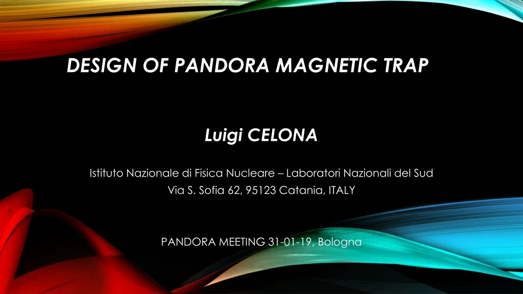
Design of PANDORA MAGNETIC Trap. Luigi CELONA Istituto Nazionale di Fisica Nucleare – Laboratori Nazionali del Sud Via S. Sofia 62, 95123 Catania, ITALY PANDORA MEETING 31-01-19, Bologna. TRAP PRELIMINARY DEFINTION. 07/03/2017. TRAP PRELIMINARY DEFINTION.

E N D
Design of PANDORA MAGNETIC Trap Luigi CELONA Istituto Nazionale di Fisica Nucleare – Laboratori Nazionali del Sud Via S. Sofia 62, 95123 Catania, ITALY PANDORA MEETING 31-01-19, Bologna
TRAP PRELIMINARY DEFINTION 07/03/2017
PANDORA: innovative trap NEEDED!!! Spectropolarimeters • WHISHLIST: • Radial access (HPGe ,optical,…) → Number, location and port dimensions should be fixed to start the design • High axial and radial confining fields • Beam extraction is needed? • ISSUES: • Hexapole limits the access for diagnostics • Costs Hexapole + SC - coils
POSSIBLE ROADMAP • Instead of a single cryostat for the source coils, twoseparatedcryostatsmay be used for the solenoids (symmetricalstructure) to leave in the middle the radial access. Higher cost! • To achieve the radial access through the hexapoledifferent strategies may be useddepending from the chosentechnology: • If the field isachievedthrough PM the degradation of the radial field due to the emptyspace must be estimated. • If the field isachievedthrough a coil basedhexapole the spacebetween the conductorsmay be used • In any case itisbetter to keep the chamberseparated from the radialmagnetic system.
POSSIBLE ROADMAP #2: IRIS STRUCTURE • A possibleapproach to achieve a higherradial field in case of RT hexapoleis to reshape the plasma chamber. Sext-in-Sol magnetic field structure New-shaped" plasma chamber
IRIS: PRELIMINARY CALCULATIONS AISHahexapole. Only 2 materials needed with the grain boundary diffusion (Tb) process. Green= VAC 745 HR Blue= VAC677 HR Originalhexapoleprovides 1.3 T @ 46 mm
IRIS: PRELIMINARY CALCULATIONS • Fields generated by SC coils can cause a local demagnetization of the hexapole. Avoided with grain boundary diffusion process! • Temperature of external part of plasma chamber MUST be kept low to avoid demagnetization Demagnetizationissues
IRIS: PRELIMINARY CALCULATIONS AISHahexapolegroovedaccording to plasma chambershape.
IRIS: PRELIMINARY CALCULATIONS 1.2 T@49 mm
PANDORA: innovative trap design • PRO: • Larger radial access for diagnostic • No axial losses • CONS: • Setup much more complex and expensive • Beam extraction need to be further studied Details reported in Claudia’s talk. To be investigated: Radial field lower wrt the classical ECRIS, confinement for HCI need to be studied
NEXT STEPS • Definition of the trapstronglydepends from: • detailed list of portsneeded and their location; • Radialconfining field on plasma chamberwalls; • ECRIS, ECRIT or TARALLO-like? • Budget available; BOUNDARY CONDITIONS NEEDED • Trap design isexpected for end 2019