Download

1 / 16
160 likes | 246 Views
The new ITER-like Wall in-vessel components. What are the constraints?. W-coated CFC: Risk factor: carbidisation… interlayer embrittlement… failure Limit steady state to 1200 o C initially Limit transients to 330 kJ/m 2 to be confirmed Be: Risk factor: melting ~1240 o C

E N D
The new ITER-like Wall in-vessel components
What are the constraints? W-coated CFC: Risk factor: carbidisation… interlayer embrittlement… failure Limit steady state to 1200o C initially Limit transients to 330 kJ/m2 to be confirmed Be: Risk factor: melting ~1240oC Limit steady state to 950oC Limit transients to 20 MJ/m2/s1/2 from literature Bulk W: Risk factor: crystallization Limit steady state surface to 1200oC initially, 2200oC later on possibly (this takes stressed region to 1200oC) Risk factor: macro deformation, UFO… Limit springs to 350oC or 60 MJ/m2 (with TWF=1) Limit transients to 20 (MJ/m2)/s1/2 from literature Min density for NBI Compatible with ohmic limiter phase Generous GAPS initially Caution with RF/LH localised load Max ELM size
Bulk W LBSRP • Surface temperature limit: initially 1200oC (avoid recrystallisation), later 2200oC • Wedge temperature (600oC, or 72 MJ/m2) • Springs (under investigation, probably 350oC, or <60 MJ/m2)… sweeping might be necessary • ELMs (literature) 20 MJ/m2/s1/2
Bulk W LBSRP P Lomas + S Jachmich Toroidal wetted area affected by: gaps between stacks and their shadowing, gaps between lamella and their shadowing. Toroidal conductivity within stack very small: heat goes straight down to springs.
Bulk W LBSRP MARION tests at >58 MJ/m2 with thermal barrier above spring (stack 1-2-3) confirm this is sufficient to stay <330oC, stack 4 to be investigated. P Mertens et al
W-coated divertor tiles • Surface temperature limit: initially 1200oC • Energy limit ~unchanged (minor effect on inter-pulse cooling, low e) • ELMs (under investigation)
W-coated divertor tiles - ELMs 100x, 1 ms long, JUDITH shots C Thomser et al
W-coated divertor tiles - ELMs 100x, 1 ms long, JUDITH shots C Thomser et al
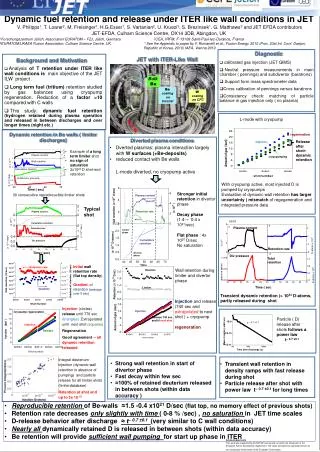
Be inner top: Melting: MIGHT be limiting with high triangualrity, high proximity of second X-point, high flux expansion… Be inner and outer limiter: Melting: OK with ohmic ramp-up and ramp-down OK with sufficiently large gaps Incompatible with plasma contact during heating phase MIGHT suffer with localised RF loads Beryllium main chamber Limiter – bidirectional / Divertor - unidirectional
Beryllium operational limits Max input power has been estimated for 5 DESIGN LIMITER configurations and 3 X-point configurations to stay within Be melting limits CEA under TA Constant: 6 MW/m2 x 10 s OR 8.4 MW/m2 x 5 s Ramp (to/from): 10 MW/m2 x 10 s OR 14 MW/m2 x 5 s
Be: ohmic ramp up+down always OK Assuming power always peaks on the same tile, which will not be the case. Power density can be translated in surface temperature for “any” loss power (t):
… a generic problem of high triangularity scenarios Be: high-d X-point might overload SC V_4M5_LT: OK everywhere 3MA5_HT3: high loads on SC(UI) and DP – not cured analytically so far 3MA5_ITER: high loads on SC(UI) – not cured analytically so far 3MA5_ITER: high loads outer wall – OK if ROG increased by 1 cm
Beryllium transient limits Be melt threshold ~20 MJ/m2/s1/2 Unlikely to have ELMs with such a severity in the main chamber Disruptions of sufficient severity are possible V Riccardo and A Loarte, NF 45, p.1427-1438 C1-C19 Residual fraction only for PTN energy >1 MJ Fast ITB collapses now rare, but not completely vanished (4 in 2009)
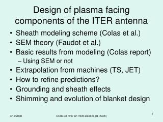
Neutral beams • Normal bank (IWGL+IWC): • Surface temperature limit on W-coated CFC tiles • Bulk temperature limit on fixings and W-coating at cork (60 MJ/m2) • Tangential bank (various inner and outer wall locations): • Be melting (IWGL apex + WPL) • Surface temperature limit on W-coated CFC tiles (IWGL wing + SC trays +… ) • pre-existing weak points (knuckles, bolts… ) same or improved limits Where are the ILW constraints?
Inner wall NBI footprints Outer wall NBI footprints Colour code (typical): W-coated CFC and berylliumPower density on footprint edge: 0.5 and 1.0 MW/m2 NBI revised operational limits
What are the constraints? W-coated CFC: Risk factor: carbidisation… interlayer embrittlement… failure Limit steady state to 1200o C initially Limit transients to 330 kJ/m2 to be confirmed Be: Risk factor: melting ~1240oC Limit steady state to 950oC Limit transients to 20 MJ/m2/s1/2 from literature Bulk W: Risk factor: crystallization Limit steady state surface to 1200oC initially, 2200oC later on possibly (this takes stressed region to 1200oC) Risk factor: macro deformation, UFO… Limit springs to 350oC or 60 MJ/m2 (with TWF=1) Limit transients to 20 (MJ/m2)/s1/2 from literature Min density for NBI Compatible with ohmic limiter phase Generous GAPS initially Caution with RF/LH localised load Max ELM size