Download

1 / 19
200 likes | 372 Views
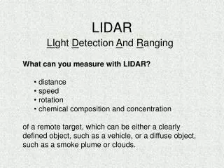
Nodding LIDAR. For Applied Research Associates By Roscoe Kane and John Barton. Overview. Background Solution Design Software Project Management. Background. LIDAR stands for Li ght D etection A nd R anging

E N D
Nodding LIDAR For Applied Research Associates By Roscoe Kane and John Barton
Overview Background Solution Design Software Project Management
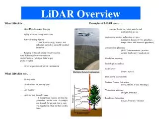
Background • LIDAR stands for Light Detection And Ranging • Emits a pulsed laser beam and measures the time between emission and return to determine distance • Most systems are at best 2 dimensional, with 1 axis of sweep that returns 1 dimension of range
Problem Statement • Develop a system to adapt a 2 dimensional LIDAR system into a 3 dimensional LIDAR system by adding a second axis of rotation • Do this by nodding the system up and down in a sinusoidal pattern
Specs • 30º minimum sweep angle • .5hz minimum scan rate • Capable of any orientation • Capable of being disabled • Safety for both humans and robot • Bolts to table for display
Specs Down 30 deg. In ≤ 1 sec Up 30 deg. In ≤ 1 sec Works if mounted in any orientation Bolts for mount to table
Our Solution • Move the entire system about it’s center of gravity • Use a resonant spring oscillator to generate an constant frequency and allow for a smaller motor • Use a Maxon motor and motor controller to start, stop and maintain oscillation
Movement of LIDAR Unit Axis of Scan Axis of Sweep More then 30 scans per sweep Sweep is primary axis
System Diagram 24V Power Supply Spring LIDAR Motor Encoder Power Flow Motor Controller PC Data Flow Mechanical Drive
Mechanical Design The LIDAR bracket mounts the LIDAR system and rotates with it. The base holds the bracket up and serves as a referenced for both the motor and spring to act on.
Spring Sizing • The model for our mechanical system is shown below, where the arrow shows our motor input • The size of the spring affects the natural frequency of the system
Spring Sizing There are many ways to design a spring for a system We tried first calculating the spring constant, but were unable to purchase a spring using that value Next we tried calculating the physical size of the spring, but were unable to get a plausible value from any available spring sizing calculations Finally, we simply ordered a few springs that should add up to approximately the spring constant we need This way we can add or remove springs to adjust the spring constant, and subsequently the natural frequency
Software Development The programming was made much easier because the motor controller came with a DLL of functions that control position, velocity and acceleration very simply The functions can also control velocity and position in a profile, either trapezoidal or sinusoidal
Functions in a DLL The functions to control our motor are inside a managed DLL The code to use functions inside a DLL was difficult to find
Data Correlation Motor encoder data is time stamped and saved LIDAR data is given correlated with the encoder data based on the timestamp