Download
1 / 26
260 likes | 430 Views
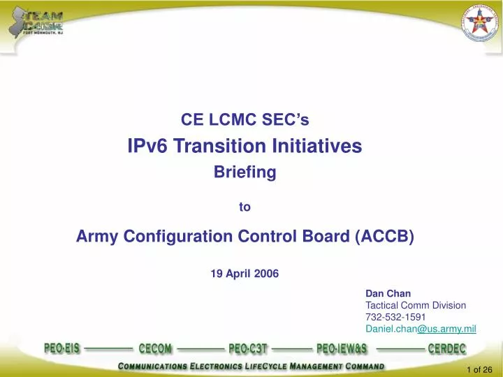
CE LCMC SEC’s IPv6 Transition Initiatives Briefing to Army Configuration Control Board (ACCB). 19 April 2006. Dan Chan Tactical Comm Division 732-532-1591 Daniel.chan @us. army.mil. Briefing Objectives. Inform on current IPv6 mandates and status of DoD and Army goals.

E N D
CE LCMC SEC’s IPv6 Transition Initiatives Briefing to Army Configuration Control Board (ACCB) 19 April 2006 Dan Chan Tactical Comm Division 732-532-1591 Daniel.chan@us.army.mil
Briefing Objectives • Inform on current IPv6 mandates and status of DoD and Army goals. • Provide an overview of SEC’s IPv6 initiatives and efforts • Provide technical details of SEC’s IPv6 Pilot Project
IPv6 Policy Mandates • DoD CIO -- June 2003 • Established goal of FY 08 to complete the transition to IPv6 • Prohibited use of IPv6 on operational networks until IA risk assessment was complete • DoD CIO -- September 2003 • Established policy that products and systems procured or acquired after October 1, 2003 must be IPv6 capable • Office of Management and Budget -- August 2005 • Established June 2008 by which all federal agencies’ infrastructure (network backbones) must be using IPv6
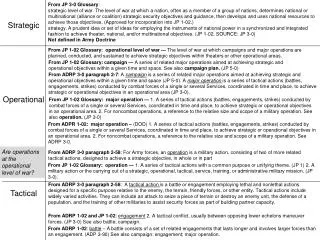
Phase 1 (FY04-FY10) Phase 2 (FY10-FY13) IPv6 Dominant FY06 FY04 FY07 FY05 FY08 FY09 FY10 FY12 FY13 Post FY13 1 1 4 1 2 4 1 2 1 3 2 4 3 4 2 3 2 4 3 1 4 2 3 4 1 2 3 1 2 3 4 3 4 1 2 3 IPv4 and IPv6 Coexistence Period Post FY14 Coexist Fade Application Transition (via Tech Refresh) Infrastructure (Core) Upgrades (via I3MP) MACOM Transition (via Tech Refresh) PEO Transition (via Tech Refresh) Procure IPv6 Capable Equipment SWB 4 NOTIONAL -- CONTINGENT ON VALIDATION OF ASSUMPTIONS AND FUTURE TACTICAL NETWORK INTEGRATED PLAN IPv4 Native IPv6 Capable IPv6 Dominant Army IPv6 Timeline
IPv6 Transition Application Demo Project Purpose • Establish SEC as an active participant and contributor to Army and DoD strategic plans for IPv6 Transition • Demonstrate as a viable proof of concept and feasibility to transition a legacy tactical system’s messaging application to IPv6 compliant by leveraging capabilities/expertise across C4ISR community • Elevate workforce’s awareness on DoD/OMB/Army’s IPv6 transition mandate, provide IPv6 training to C4ISR managers and engineers, and create a channel for IPv6 knowledge/information exchange within the C4ISR communities Accomplishments • Developed an Application Layer Gateway (ALG) for the MCS-L CommServer to successfully transitioned MCS-L messaging to IPv6 compliant. • Elevated awareness within SEC/SED workforce and Fort Monmouth Community • SEC/SEC Workforce Training: 7 February 2006 • CE LCMC Workforce Training: 8 February 2006 • Pilot Project Demonstration: 6 Feb 2006 • Establishment of an IPv6 web portal on AKO which consists of a forum, news, calendar of events schedule, archived documents, and links to other relevant IPv6 sites • Leveraged from S&TCD IPv6 laboratory capability, PM GCC2 and PM TRCS assets, SEC’s BSSD & ABSD, and ILEX/Telcordia and SRI expertise
IPv6 Pilot Project Team • Systems Soft Mgt • Soft Apps Mgt • Security, i.e. IAVAs • Soft Config Mgt • Soft Mgt Support • ILEX/Telcordia Team PM TRCS Support PM GCC2 Support Software Development and Sustainment Management Software Engineering Support Communication and Network System Engineer. • Army IPv6 Lab since 2000 • DoD SME collaborating with Industry and Academia • Participant of DoD and Industry Test Beds, i.e. MoonV6 • Designated developer of Army IPv6 Transition Plan • Commissioned by DoD, CIO/G-6, G8, SEC, PM WIN-T, and PdM CHS to conduct research, M&S analyses, testing, training on IPv6 • SRI Team Soft Engineers & Comp Scientists Support
IPv6 Transition ApplicationLive Demo Demo Essentials • Migrated legacy MCS-L messaging capability to make it capable to operate in an IPv6 environment in peer-to-peer mode through Dual-Stacking, Tunneling, and Translation technologies • Developed a transition methodology which may be replicated over other similar systems • Network topology illustrates a configuration hosted in a current system (NOC-V) and depicting a legacy application (MCS-L) being IPv6 capable and interoperable • Demonstration of 6 different interoperability test scenarios capturing a complete cross-section within a IPv4/IPv6 environment with MCS-L passing JVMF messages
MCS-L w/ALG (Dual Stack) Army’s SBTC or FCS Notional IPv6 Pilot Project Legacy Application (MCS-L) Army’s Tactical Networks Network Management System (NOC-V) IPv4 Seamless Connectivity IPv6
SINCGARS / EPLRS SWLAN Network Operation Center – Vehicle (NOC-V) Current Configuration NOC-V GPS EPLRS NM QEAM 2 NTDR QEAM 1 Satellite Van (TSC-85/93, SMART-T START-T) to BSN GBS Dish 100 Base FX S2/S3 vehicle FBCB2 FSE 100 Base FX TOC Server • Local Voice Services • 19 Analog Phones Voice Circuits 10 Base 2 MSE SUI LAN Access • Network Management Client • Sun Ray 1 GBS Video Access • Network Management Client • Sun Ray 2 FBCB2 SVGA Display Access Cisco 2950C E-net Switch SWLAN Black-Side Management Laptop ISYSCON (V)4 (TIM) Laptop MCS Light Tent Area ENM Laptop
EPLRS Network Operational Scenario – Upgraded MCS in Hybrid Network NOC-V MCS 4 Remote TOC with legacy IPv4 MCS EPLRS Cisco 2924M Cisco 2912MF Cisco 2950C E-net Switch MCS 6 Remote TOC with new IPv6-only MCS MCS-6/4 Tent Area MCS with Application Layer Gateway (ALG)
Virtual / Live Gateway Virtual / Live Gateway OPNET Future Force IPv6 Core WIN-T/FCS Demo Scenario with Upgraded MCS in Hybrid Network Node 3 NOC-V IPv6 / IPv4 Core (WIN-T / JTRS) Remote TOC with legacy IPv4 MCS Cisco 2924M BSD dual-stacked router) Cisco 2912MF Cisco 2950C E-net Switch Node 1 Node 2 MCS-6/4 Tent Area Simulated TOC with an IPv6-only MCS and virtual IPv6 Core Infrastructure MCS-6/4 with Application Layer Gateway (ALG)
IPv4 Demo Scenario 1 (Operational View) Sustain IPv4 Legacy Baseline Interoperability Node 3 NOC-V IPv6 / IPv4 Core (WIN-T / JTRS) Remote TOC with legacy IPv4 MCS Cisco 2924M BSD dual-stacked router Cisco 2912MF Virtual / Live Gateway OPNET Future Force IPv6 Core WIN-T/FCS Cisco 2950C E-net Switch Node 1 Node 2 Virtual / Live Gateway MCS-6/4 Tent Area MCS-6/4 with Application Layer Gateway (ALG) Simulated TOC with an IPv6-only MCS and virtual IPv6 Core Infrastructure
IPv4 Legacy Network Core IPv4 Virtual Live Gateway Virtual Live Gateway Demo Scenario 1 Sustain IPv4 Legacy Baseline Interoperability Node 2 Virtual Environment Live Network MCS with 6/4 Comm Server Node 1 Node 3 OPNET Future Force IPv6 Core WIN-T/FCS IPv6 MCS Legacy MCS BSD Dual-stacked Router IPv4 JVMF Messages • Purpose: Demonstrate that the MCS with 6/4 CommServer retains IPv4 legacy operational functionalities • MCS with 6/4 CommServer (node 2) exchanges JVMF message with Legacy MCS (node 3) • Node 2 initiates JVMF message addressed to node 3 • 6/4 CommServer recognizes destination address of URN as IPv4 and adds IPv4 header • Message traverses IPv4 legacy core network (i.e., router or NOC-V) • Node 3 receives, processes, and displays message • Repeat with message originating from the legacy MCS
IPv6 Virtual / Live Gateway Virtual / Live Gateway OPNET Future Force IPv6 Core WIN-T/FCS Demo Scenario 2 (Operational View) Send and Receive IPv6 JVMF Messages Node 3 NOC-V IPv6 / IPv4 Core (WIN-T / JTRS) Remote TOC with legacy IPv4 MCS Cisco 2924M BSD dual-stacked router Cisco 2912MF Cisco 2950C E-net Switch Node 1 Node 2 MCS-6/4 Tent Area MCS-6/4 with Application Layer Gateway (ALG) Simulated TOC with an IPv6-only MCS and virtual IPv6 Core Infrastructure
IPv4 Legacy Network Core IPv6 Virtual Live Gateway Virtual Live Gateway Demo Scenario 2Send and Receive IPv6 JVMF Messages Node 2 Virtual Environment Live Network MCS with 6/4 Comm Server Node 1 Node 3 OPNET Future Force IPv6 Core WIN-T/FCS IPv6 MCS Legacy MCS BSD Dual-stacked Router IPv6 JVMF Messages • Purpose: Demonstrate that IPv6 JVMF messages can be transmitted, received, and processed between the 6/4 CommServer (node 2) and an IPv6-only MCS client • MCS with 6/4 CommServer (node 2) exchanges JVMF message with IPv6-only MCS via the virtual network • Node 2 initiates a JVMF message addressed to node 1 • 6/4 CommServer recognizes destination address of URN as IPv6, adds IPv6 header, and sends message to virtual / live gateway (VLG) • The VLG processes the message and transmits it through the virtual network to the IPv6-only MCS host. • Repeat with message originating from Node 1.
Virtual / Live Gateway Virtual / Live Gateway OPNET Future Force IPv6 Core WIN-T/FCS Demo Scenario 3 (Operational View) Exchange IPv6 / IPv4 JVMF Message via Transport Relay Translator IPv4 Node 3 NOC-V IPv6 IPv6 / IPv4 Core (WIN-T / JTRS) Remote TOC with legacy IPv4 MCS Cisco 2924M BSD dual-stacked router Cisco 2912MF Cisco 2950C E-net Switch Node 1 Node 2 MCS-6/4 Tent Area Simulated TOC with an IPv6-only MCS and virtual IPv6 Core Infrastructure MCS with ALG and Transport Relay Translation (TRT)
IPv4 Legacy Network Core Virtual Live Gateway Virtual Live Gateway Demo Scenario 3Exchange IPv6 / IPv4 JVMF Message viaTransport Relay Translator Node 2 Virtual Environment IPv4 Live Network TRT IPv6 MCS with 6/4 Comm Server Node 1 Node 3 OPNET Future Force IPv6 Core WIN-T/FCS IPv6 MCS Legacy MCS BSD Dual-stacked Router IPv6 / IPv4 Relayed JVMF Messages • Purpose: Demonstrate that the MCS 6/4 can transparently translate and forward a message from an IPv4 node (node 3) to an IPv6 node (node 1) and vice-versa. Node 2 acts as a Transport Relay Translator (TRT) in this scenario. • Node 3 sends a single JVMF message to node 1 • Node 3 initiates a JVMF message addressed to node 1 (but URN table points to node 2). • The 6/4 CommServer receives the message and notices that the destination URN is not its own. • It then looks up the IP address of the destination URN (node 1 in this case) and sends the message on its way. • Node 1 receives, processes, and displays the JVMF message • Repeat with message originating from node 1
Virtual / Live Gateway Virtual / Live Gateway OPNET Future Force IPv6 Core WIN-T/FCS Demo Scenario 4 (Operational View) Multi-Destination Unicast JVMF Messages in a 6/4 Hybrid Environment IPv4 Node 3 NOC-V IPv6 IPv6 / IPv4 Core (WIN-T / JTRS) Remote TOC with legacy IPv4 MCS Cisco 2924M BSD dual-stacked router Cisco 2912MF Cisco 2950C E-net Switch Node 1 Node 2 MCS-6/4 Tent Area Simulated TOC with an IPv6-only MCS and virtual IPv6 Core Infrastructure MCS with Application Layer Gateway (ALG)
IPv4 Legacy Network Core Virtual Live Gateway Virtual Live Gateway Demo Scenario 4Multi-Destination Unicast JVMF Messagesin a 6/4 Hybrid Environment Node 2 Virtual Environment IPv4 Live Network MCS with 6/4 Comm Server IPv6 Node 1 Node 3 OPNET Future Force IPv6 Core WIN-T/FCS IPv6 MCS Legacy MCS BSD Dual-stacked Router IPv6 Unicast JVMF Message IPv4 Unicast JVMF Message • Purpose: Demonstrate that the 6/4 MCS can distribute a single JVMF message to a mix of IPv4 and IPv6 clients • Node 2 distributes a single JVMF message to an IPv6 node (node 1) and an IPv4 node (node 3) • Node 2 initiates a JVMF message addressed to nodes 1 and 3 • 6/4 CommServer reads the URN for each destination and adds the appropriate v4 or v6 header for each outgoing message • Each destination node receives, processes, and displays the JVMF message
IPv4 multicast Virtual / Live Gateway Virtual / Live Gateway IPv6 multicast OPNET Future Force IPv6 Core WIN-T/FCS Demo Scenario 5 (Operational View) Multicast JVMF Messages in 6/4 Hybrid Environment Node 3 IPv6 / IPv4 Core (WIN-T / JTRS) NOC-V Remote TOC with legacy IPv4 MCS BSD dual-stacked router with Multicast (rendezvous point) Cisco 2924M Cisco 2912MF Cisco 2950C E-net Switch Node 1 Node 2 MCS-6/4 Tent Area MCS with Application Layer Gateway (ALG) Simulated TOC with an IPv6-only MCS and virtual IPv6 Core Infrastructure
IPv4 Legacy Network Core Virtual Live Gateway Virtual Live Gateway Demo Scenario 5 Multicast JVMF Messages in 6/4 Hybrid Environment Node 2 Virtual Environment IPv4 Live Network MCS with 6/4 Comm Server IPv6 Node 3 Node 1 OPNET Future Force IPv6 Core WIN-T/FCS IPv6 MCS Legacy MCS BSD Dual-stacked Router with Multicast IPv4 Multicast JVMF Message IPv6 Multicast JVMF Message • Purpose: Show that multicasting can be performed by a 6/4 MCS without loss of efficiency, i.e., one originating message distributed to all multicast members • Node 2 initiates a single multicast message to all multicast member – in this case, a v4-only node (node 3) and a v6-only node (node 1) • Node 2 initiates a single IPv6 multicast message addressed to the multicast group • The BSD multicast router determines the URN of each multicast member, recognizes the IP version of each member, and redistributes the message accordingly. • Each destination node receives, processes, and displays the multicast message
Virtual / Live Gateway Virtual / Live Gateway OPNET Future Force IPv6 Core WIN-T/FCS IPv6 MCS Demo Scenario 6 (Operational View) v6-over-v4 Automatic Tunnel Broker IPv4-only Core IPv6-only Core NOC-V IPv4-only Router Tunnel Broker IPv4 IPv6 Cisco 2924M 6-over-4 Tunnel Cisco 2912MF Cisco 2950C E-net Switch Node 2 Node 1 MCS-6/4 with TB client Tent Area MCS IPv6-only MCS with Application Layer Gateway (ALG)
Virtual Live Gateway Virtual Live Gateway Demo Scenario 6 v6-over-v4 Automatic Tunnel Broker Live Network Virtual Environment Tunnel Broker IPv4 IPv6 Node 1 IPv4 Legacy Network Node 2 OPNET Future Force IPv6 Core WIN-T/FCS IPv6 MCS IPv6-only MCS with TB Client IPv6 Router IPv4-only Router 6-over-4 Tunnel • Purpose: Demonstrate how a tunnel broker can be used to traverse a legacy IPv4 network when both communicating endpoints are IPv6 applications • Node 2 establishes a communication session with node 1. A 6-over-4 tunnel is transparently set up between the tunnel broker (TB) and the TB client • Node 2 determines its interface is IPv4 but its destination is IPv6 • TB client negotiates a 6-over-4 tunnel with the TB • Outgoing IPv6 message from node 2 is encapsulated in IPv4 header to create a tunnel and transmits the message onto the IPv4 network. • The TB unwraps the IPv4 tunnel header and retransmits the message across the IPv6 network. • Node 1 receives, processes, and displays the message.
Dual stack is main approach. Insert via Tech Refresh Applications (Must be able to use either v4 or v6 transport) Host Operating Systems Routers (via “integrated dualstack” ) Servers (Including DNS), and Application Layer Gateways (ALGs) for communications gateways between C4ISR enclaves Configured Tunnels Brokered Automatic Tunneling Translation as a mechanism of last resort for legacy devices Demo Summary
Conclusion • The demo project represents only one transition solution but more evaluations and investigations will need to be explored • The Army Community needs to evaluate all possible impacts when transitioning to IPv6 • SEC IPv6 Team can provide technical support if requested • IPv6 Web Portal in AKO to serve as a channel for exchange of knowledge https://www.us.army.mil/suite/portal.do?$p=247087 • SEC POC: Dan Chan daniel.chan@us.army.mil Bruce Weimer bruce.weimer@us.army.mil